


SERVICING
59
Alternately, the system CFM can be determined by operating
the electric heaters and indoor blower WITHOUT having the
compressor in operation. Measure the temperature rise as
close to the blower inlet and outlet as possible.
If other than a 240V power supply is used, refer to the BTUH
CAPACITY CORRECTION FACTOR chart below.
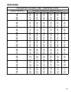
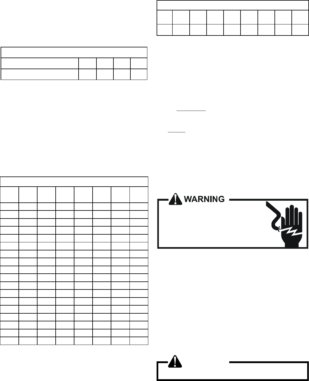
BTUH CAPACITY CORRECTION FACTOR
SUPPLY VOLTAGE 250 230 220 208
MULTIPLICATION FACTOR 1.08 .92 .84 .75
EXAMPLE: Five (5) heaters provide 24.0 KW at the rated
240V. Our actual measured voltage is 220V, and our
measured temperature rise is 42°F. Find the actual CFM:
Answer: 24.0KW, 42°F Rise, 240 V = 1800 CFM from the
TEMPERATURE RISE chart on the right.
Heating output at 220 V = 24.0KW x 3.413 x .84 = 68.8
MBH.
Actual CFM = 1800 x .84 Corr. Factor = 1400 CFM.
NOTE: The temperature rise table is for sea level installa-
tions. The temperature rise at a particular KW and CFM will
be greater at high altitudes, while the external static pressure
at a particular CFM will be less.
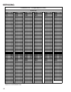
TEMPERATURE RISE (F°) @ 240V
CFM
4.8
KW
7.2
KW
9.6
KW
14.4
KW
19.2
KW
24.0
KW
28.8
KW
600 25 38 51 - - - -
700 22 33 43 - - - -
800 19 29 38 57 - - -
900 17 26 34 51 - - -
1000 15 23 30 46 - - -
1100 14 21 27 41 55 - -
1200 13 19 25 38 50 - -
1300 12 18 23 35 46 - -
1400 11 16 22 32 43 54 65
1500 10 15 20 30 40 50 60
1600 9 14 19 28 38 47 57
1700 9 14 18 27 36 44 53
1800 8 13 17 25 34 42 50
1900 8 12 16 24 32 40 48
2000 8 12 15 23 30 38 45
2100 7 11 14 22 29 36 43
2200 7 11 14 21 27 34 41
2300 7 10 13 20 26 33 39
HTR
KW
3.0
KW
4.7
KW
6.0
KW
7.0
KW
9.5
KW
14.2
KW
19.5
KW
21.0
KW
BTUH 10200 16200 20400 23800 32400 48600 66500 71600
ELECTRIC HEATER CAPACITY BTUH
FORMULAS:
Heating Output = KW x 3413 x Corr. Factor
Actual CFM = CFM (from table) x Corr. Factor
BTUH = KW x 3413
BTUH = CFM x 1.08 x Temperature Rise (T)
CFM = KW x 3413
1.08 x T
T = BTUH
CFM x 1.08
S-61A CHECKING HEATER LIMIT CONTROL(S)
Each individual heater element is protected with a limit
control device connected in series with each element to
prevent overheating of components in case of low airflow.
This limit control will open its circuit at approximately 150°F.
HIGH VOLTAGE!
Disconnect ALL power before servicing
or installing. Multiple power sources
may be present. Failure to do so may
cause property damage, personal injury
or death.
1. Remove the wiring from the control terminals.
2. Using an ohmmeter, test for continuity across the nor-
mally closed contacts. No reading indicates the control
is open - replace if necessary.
IF FOUND OPEN - REPLACE - DO NOT WIRE AROUND.
S-61B CHECKING HEATER FUSE LINK
(OPTIONAL ELECTRIC HEATERS)
Each individual heater element is protected with a one time
fuse link which is connected in series with the element. The
fuse link will open at approximately 333°.
WARNING
Disconnect ALL power before servicing.
1. Remove heater element assembly so as to expose fuse
link.