


Installation
309572ZAG 21
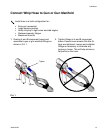
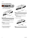
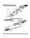
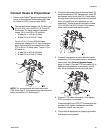
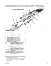
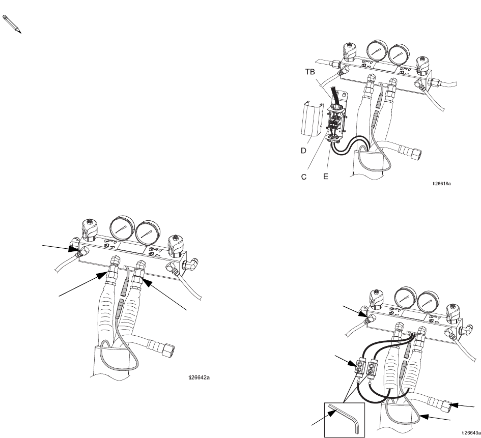
Connect Hoses to Proportioner
1. Grease with Fusion
®
grease and connect fluid
hoses to proportioner fluid manifold (M). Red
for hardener (ISO), blue for resin (RES).
NOTE: For proportioners with termination box
(TB), follow step 2, For proportioners with electrical
splice connectors (12) follow step 3.
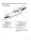
2. Connect hose power wires to terminal block (C)
on termination box (TB). Remove box cover (D)
and loosen lower strain relief (E). Route wires
through strain relief and fully insert into terminal
block (A and B hose wire positions are not
important). Torque terminal connector screws
(C) to 26-30 in-lb (2.9-3.3 N•m). Fully tighten
strain relief screws and replace cover.
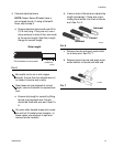
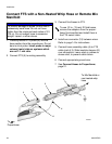
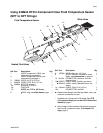
3. Connect hose power wires to electrical splice
connectors (12) from proportioner or accessory
control box. See Connect Heated Hoses,
page 14, step 5. Connect FTS hose cable (4) to
cable from proportioner or accessory control
box. Wrap connections with electrical tape.
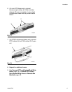
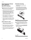
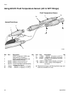
4. Connect FTS cable connectors. Fully tighten
RTD connectors, if provided.
If thermocouple (non-RTD) FTS connectors are
provided, fully tighten connectors and slide
connector covers over the joint.
5. Check that all equipment is properly grounded.
See proportioner manual.
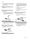
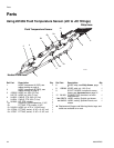
The manifold hose adapters (N, P) allow use
of 1/4 in (6.4 mm). and 3/8 in. (9.5 mm) ID
fluid hoses. To check adapter tightness,
torque 1/4 in. and 3/8 in. ID hoses to:
• A side (N) to 14 ft-lb (19 N•m).
• B side (P) to 20 ft-lb (27 N•m).
To use 1/2 in. (13 mm) ID fluid hoses,
remove the adapters (N, P) from the propor-
tioner fluid manifold and install them in the
FTS or 3/8 in. ID hose inlets. Torque 1/2 in.
ID hoses to:
• A side (N) to 43 ft-lb (58 N•m).
• B side (P) to 55 ft-lb (74 N•m).
M
N
P
M
4
3
12
T