


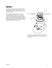
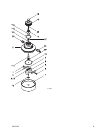

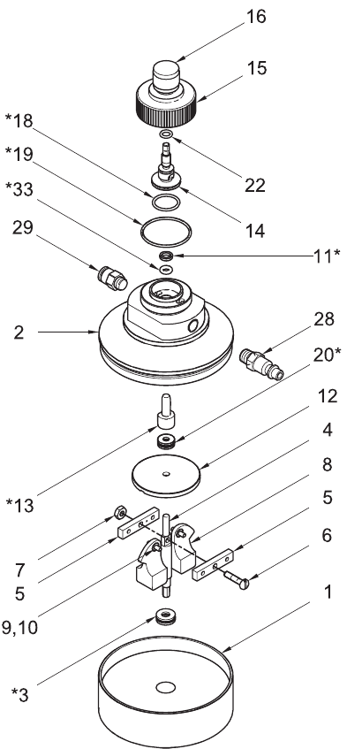
Repair
NOTE: To repair the agitator, see your separate
agitator manual.
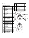
NOTE: Repair Kit 24J886 is available. Order the kit
separately. Kit parts are marked with an asterisk, for
example (3*). For the best results use all the parts
in the kit.
NOTE: Use multi-purpose lithium based grease
where ever lubrication is required. Order Part No.
111920.
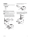
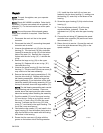
1. Disconnect the main air line to the speed
controller.
2. Disconnect the tube (27) connecting the speed
controller and air motor.
3. Unscrew the adjustment nut (15) from the upper
housing (2). Turn the knob (16) fully clockwise
(inward) to access the o-ring (18) on the bottom
plate of the seat (14). Remove the o-ring and
replace with the new o-ring (18*). Lubricate the
o-ring.
4. Remove the large o-ring (19) on the upper
housing (2). Replace with a new o-ring (19*).
Lubricate the o-ring.
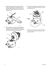
5. Unscrew the upper housing (2) from the lower
housing (1). The drive shaft (4) and cam arms (8)
may come out of the lower assembly.
6. Remove the two ball bearing assemblies (3, 20)
from the drive shaft (4). Replace with the new
ball bearing assemblies. Install the larger ball
bearing assembly (3) on the bottom of the shaft.
Install the smaller ball bearing assembly (20*) on
the top of the shaft, above the large washer (12).
NOTE: The ball bearing assemblies each consist
of one bearing and two washers. Place one
washer above the bearing and the other washer
below the bearing before installing the assembly.
7. Push the needle (13) out of the upper housing
(2) from the top. Using an o-ring pick, remove
the u-cup (11) and o-ring (33) from the upper
housing. Lubricate the new o-ring (33*) and
u-cup (11*) and install in the upper housing. The
lips of the u-cup must face up.
8. Lubricate the new needle (13*) and install in the
upper housing (2) from the bottom, being sure to
align the flat face on the needle with the mating
flat surface in the housing.
9. Ensure that the cam arms (8) align with the
groove on the bottom side of the large washer
(12). Install the drive shaft (4) and cam arm
assembly into the lower housing (1), making sure
the bearing (3*) seats fully in the recess of the
housing.
10. Screw the upper housing (2) fully onto the lower
housing (1).
11. Turn the adjustment knob (16) all the way
counterclockwise (outward). Screw the
adjustment nut (15) fully onto the upper housing
(2).
12. Connect the air tubing (27) between the speed
controller tube connector (29) and the air motor
tube connector (21).
13. Return the unit to service. Connect the main air
line to the quick-disconnect fitting (28) on the
speed controller.
ti17005a
3A1315A
7