


9 - 29
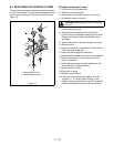
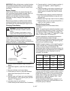
Ignition Switch
NOTE:
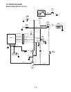
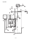
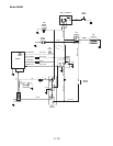
Refer to the wiring diagram of the unit involved
to determine switch functions and test using the meth-
ods described.
The ignition switch incorporates a number of functions,
although not all functions are used on all equipment.
The switch has three positions: OFF, RUN, and a
momentary contact START position. Use an ohmmeter
to check the continuity of the switch in each position.
OFF Position
- Should be continuity between contacts
G and M. These connections ground the engine
magneto and stop the engine in the OFF position.
RUN Position
- Should be continuity between contacts
B and A. These connections supply power to the rest of
the wiring harness. Connections G and M open to each
other.
START Position
- Hold switch in START position while
testing. There should be continuity between contacts
S1 and S2. These connections apply power to close
the solenoid contacts and operate the starter motor.
In addition to the above test, place the switch in the run
position and check between each contact and ground
(metal case) to be sure no terminals are grounded. If
the switch is operating properly, there will be no
continuity between contacts other that those described.
9.5 SOLENOID AND RELAYS
Solenoid and relays are both magnetically operated
devices. Both devices operate on the principle that
passing a current of electricity through a coil of wire will
create a magnetic field strong enough to attract a piece
of iron or steel. Each device uses this principle in a
slightly different manner.
Relay
- A basic relay consists of a coil of wire wound
around a soft iron (magnetic) core. When current is
passed through the coil, the core is magnetized and
pulls down on a magnetic lever. The lever in turn is
attached to several switch contacts which open or close
other electrical circuits. In this fashion, a small current
can control one or more larger electrical currents and
actuate several other devices. In most cases a relay
contact moves only a fraction of an inch and the
magnetic pull is small.
Solenoid
- A basic solenoid consists of a coil of wire
wound around a hollow tube. A magnetic core slides
inside the tube. When current is passed through the
coil, the core is pulled into the solenoid with
considerable force. With proper design, a solenoid can
exert considerable force over a distance of several
inched. A solenoid can therefore, pull a lever, close a
heavy contact, or perform other jobs that require a
straight line pull.
If a relay or solenoid fails to operate, the cause may be
either electrical or mechanical.
To check electrically, connect a voltmeter across the
coil of the device and activate the circuit that operates
the relay or solenoid. If the meter indicates no voltage
is applied, the cause is in the control circuit.
If the meter indicates proper voltage across the coil but
the device does not function, remove the power,
disconnect the wiring and check the continuity of the
coil with an ohmmeter. The meter should indicate
resistance, in the order of 3 to 5 ohms, if the coil is
intact. A high resistance indicates an open coil and a
defective device.
There are also a number of mechanical problems that
may cause the problem.
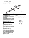
The starter solenoid in the Ariens equipment is a
sealed unit used to actuate the starter motor on the
engines. These solenoids may have three or four
connections. The two large connections carry high
current to operate the starter motor. The small
connections are connected to the coil and carry the
control current.
To check the solenoid, disconnect the cables to the
starter motor, turn the ignition switch to the start
position, and listen for the solenoid to snap inside
contacts closed.
If no snap is heard, check across the coils with a
voltmeter. The voltage should read 12 volts with the
ignition switch in the start position. If no voltage
appears, the defect is in the start circuit.
If the voltage is correct, turn off the power and check
continuity of the coil with an ohmmeter. If the coil is
open, the solenoid is defective and must be replaced.
If the coil has the proper voltage applied, and the
continuity check indicates the coil is intact, the solenoid
plunger is stuck or the contacts are welded shut and
the solenoid must be replaced.
If the solenoid snaps shut, but the start does not
operate, check across the large contacts with an
ohmmeter. If there is no continuity when the solenoid
snaps shut, the contacts are defective and the solenoid
must be replaced.
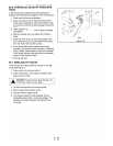
9.6 FUSES
Fuses are connected in electrical circuits to protect the
circuits from damage due to overload or short circuits.
Fuses are a "weak link" in the circuit. They contain a
metal link designed to melt when a certain current
value is exceeded thus opening or disconnecting the
wiring. Once a fuse blows or melts it must be discarded
and replaced with a new fuse of the same value.
Since the function of the fuse is to protect the circuit,
NEVER attempt to defect the protective device by
bridging or replacing with a device of a higher current
rating.
Electrical testing of these devices is simple. Since the
device either conducts current (and is therefore