


4 - 9
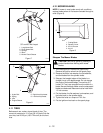
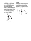
4.2 SERVICE POSITION - 260Z
To ensure the unit is positioned in the proper service
position:
1. Place unit on a flat level surface. ALWAYS stop
engine. Assure unit is secure and will not tip over.
Strap and clamp onto lift if used.
2. Place steering levers in neutral position and set
parking brake.
3. Unhook hood latches.
4. Firmly grasp engine frame and cover. Lift to
desired service position (Figure 3).
Daily Service Position:
Place engine hood prop rod
into service slot. Assure rod is engaged in slot properly.
Full Service Position:
Slowly release frame after seat
contacts foot board. Use care and be sure of your
footing. Do not step on mower deck.
5. When service is complete, lower hood and secure
with latches.
4.3 SERVICE POSITION - 250Z
Firmly grasp seat frame handle and lift past vertical.
Lay inverted seat on foot rest. When service is
complete, return seat to upright position.
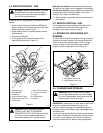
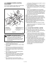
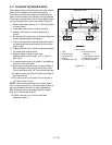
4.4 MOVING THE UNIT-ENGINE NOT
RUNNING
To move the unit without the engine running, rotate the
bypass valve levers located on the pumps toward the
center of the tractor approximately 1/2 turn using a
wrench. Levers must be returned to their original
position in order to operate the unit (Figure 4).
4.5 CLEANING AND STORAGE
IMPORTANT:
Never spray unit with water or store unit
outdoors to help prevent sealed bearing rust or
corrosion. Water can seep into sealed bearings and
reduce component life. Bearings are sealed against dirt
and debris only.
A unit that is excessively dirty should be cleaned before
work starts. Cleaning will occasionally uncover trouble
sources. Dirt and abrasive dust reduce the efficient
work life of parts and can lead to costly replacement.
WARNING:
ALWAYS block wheels and know
that jack stands or blocks used are stable,
strong, or secure and will hold the weight of
the unit during maintenance.
CAUTION:
WHEN OPENING ENGINE
COVER, USE CARE TO PROPERLY
ENGAGE PROP INTO SLOT. Be sure footing
is secure to accommodate weight shift of
hood when rotating to full service position.
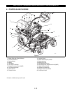
OF1811
1. Steering Levers
2. Parking Brake
3. Footboard
4. Engine Hood & Frame
5. Engine Hood Prop Rod
6. Service Slot
7. Daily Service Position
8. Full Service Position
9. Engine
10. No Step Decal
11. Battery
2
3
1
10
8
7
4
5
9
6
11
Figure 3
WARNING:
AVOID SHARP EDGES which
can cut. Movement of parts can cut off fingers
or a hand. Wrap blades, wear gloves, and use
extreme caution when servicing.
1
2
1. Left Bypass Valve Lever
2. Right Bypass Valve Lever
Figure 4
OF1730