


5
Grease Grabber™ Power Play Kitchen Exhaust Pollution Control System
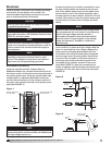
Detergent Dispenser
From the pump located on the base of the detergent
dispenser, connect a ½-inch piping connection for the
detergent supply to the 1½-inch water supply line. A
quarter turn ball valve (by others) can be installed on
this line if necessary for servicing. The connection of
the ½-inch detergent supply line to the 1½-inch water
supply line should be made within 5 feet of the cabinet
assembly.
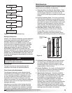
Cabinet Assembly
The unit is supplied with two (2) 1¼- or (2) 1½-inch
wash headers located at the top of the cabinet
assembly. Connect the water supply line to both of the
wash headers at the top of the cabinet. Bring a 3-inch
waste water drain piping connection with P trap to the
drain pipe on the side of the cabinet assembly. The
trap drain line water column for the drain should be
sized for the total system resistance plus 1 in. wg.
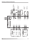
9. The remote mounted detergent dispenser frame
mounts to a foundation using the four mounting
holes located at the base of the unit. For details on
wiring this item, refer to the ELECTRICAL section.
For details on plumbing connections, refer to the
PLUMBING section.
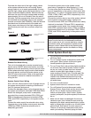
Duct Connections
Ductwork must conform to the IMC and SMACNA
guidelines.
As specified in NFPA 96, Ch. 7.5 (latest edition),
exhaust duct systems must be constructed in the
following manner; unless otherwise specified by the
local authority having jurisdiction (AHJ).
Materials
Ducts shall be constructed of and supported by
carbon steel not less than 1.37 mm (0.054 in.) (No. 16
MSG) in thickness or stainless steel not less than 1.09
mm (0.043 in.) (No. 18 MSG) in thickness.
Installation
All seams, joints, penetrations, and duct to hood collar
connections shall have a liquid-tight external weld.
An inlet transition is furnished to match the inlet duct
size. The inlet transition is furnished with a listed duct
access door for inspection and cleaning.
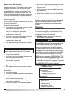
Units intended for indoor mounting are provided with
an outlet mounting flange, either at the unit discharge
or as part of a factory supplied UL 762 listed exhaust
fan. Outlet ductwork from the exhaust fan is required to
be per the above mentioned methods unless otherwise
specified by the local authority having jurisdiction
(AHJ).
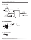
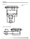
Plumbing
Once all system components are installed, plumbing
connections for the system can be made. It is
recommended that plumbing connections be done
prior to making electrical connections.
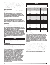
From the building, a 1½- or 2-inch (refer to drawings)
hot water line is required for connecting the wash
system. Recommended water temperature is 140˚F
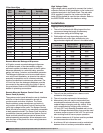
at 45 psi pressure. Refer to the chart on this page
for information on water and detergent quantity
requirements. Install the quarter turn ball valve
(provided) at the incoming water source to allow the
water to be turned off for servicing. Next, install the
strainer (provided), backflow preventer (provided),
pressure gauge (provided), and solenoid valve
(provided) respectively. Locate these items along
the incoming water line in a location convenient for
inspection/servicing.
NOTE
All water piping exposed to freezing temperatures
must to be trace heated and insulated to prevent
damage to the unit.
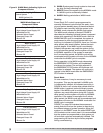
Unit Size
Wash Cycle
Water Flow
Rate (gpm)
Wash Cycle
Detergent Flow
Rate (gpm)
02-03 7.2 .36
02-04 9.6 .48
02-05 12.0 .60
02-06 14.4 .72
04-03 14.4 .72
04-04 19.2 .96
04-05 24.0 1.20
04-06 28.8 1.44
04-07 33.6 1.68
04-08 38.4 1.92
04-09 43.2 2.16
06-03 21.6 1.08
06-04 28.8 1.44
06-05 36.0 1.80
06-06 43.2 2.16
06-07 50.4 2.52
06-08 57.6 2.88
06-09 64.8 3.24
NOTE
For unit sizes 06-08 and 06-09, a minimum 2 inch
incoming water service is required.