


7
Grease Grabber™ Power Play Kitchen Exhaust Pollution Control System
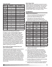
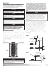
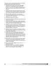
Terminate the other end of the high voltage cables
at the system cabinet on the unit housing. Ensure
enough cable is run to reach approximately 2 inches
past the high voltage spark plug terminal point on the
upper most electrostatic collector. Slide the silicone
boot over the end of the high voltage cable and strip
approximately 3/4 inch of insulation from the end of
the cable. Fold the exposed wire down and back over
the insulated end and tightly crimp on the supplied
terminal connection (See FIGURE 4). Slide the silicone
boot back over the terminal end of the cable and
firmly press onto the end of the high voltage spark
plug terminal point until the connection snaps into
place.
Exhaust Fan Motor Wiring
This unit is furnished with a remote-mounted motor
starter and an ON/OFF disconnect switch, mounted
adjacent to the fan and factory wired to the fan motor.
A three phase electrical supply must be field wired to
the motor starter, and from the motor starter to the
ON/ OFF disconnect switch. Refer to the applicable
fan installation manual for detailed instructions on
wiring the fan.
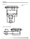
System Control Panel Wiring
Run a 120 volt, 30 amp service with 12 gauge wires to
the system control panel connecting to terminals L1
(hot), L2 (common) and ground.
Connect the detergent pump, using 14 gauge wire, to
the system control panel, terminals 1TB23 and 2TB20.
Ensure the detergent pump motor is adequately
grounded. Also connect terminals 6TB1, 6TB2, and
6TB3 at the detergent dispenser to terminals 3TB4,
4TB4, and 3TB15, respectively, in the system control
panel.
Connect the water supply line solenoid valve, using
14 gauge wire, to the system control panel, terminals
1TB26 and 2TB23. Ensure the solenoid valve is
adequately grounded.
Connect the power pack to the system control
panel using 14 gauge wire. Wire terminals 1, 2, and
3 in the power pack to terminals 1TB17, 2TB4, and
ground, respectively, in the system control panel. Wire
terminals 6, 7, 8, and 9 in the power pack to terminals
1TB16, 1TB18, 1TB15, and 1TB19, respectively, in the
system control panel.
Connect the junction box on top of the system cabinet
to the system control panel using 14 gauge wire.
Connect terminals 5TB1 and 5TB2 (access door safety
interlock) to terminals 1TB4 and 1TB13, respectively,
in the system control panel. Also connect terminals
5TB5, 5TB7 (upstream wash motor), 5TB8, and 5TB10
(downstream wash motor) to terminals 1TB21, 2TB18,
1TB22, and 2TB19, respectively, in the system control
panel.
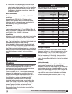
Initial System Start-Up
1. Turn off fan at motor starter disconnect, also turn
off Power Pack.
2. Turn on System Control at disconnect switch and
push green “Start” button. At this point green
normal operation light should be on.
3. Turn on Power Pack, red and clear lights should be
on at Power Pack and at System Control. If lights
are not on, check to make sure door interlock
switch is made. With high voltage on, check
meter reading at Power Pack, it should read 12kv
and approximately 1mA per linear feet of ionizer-
collector cell. Random electrical arcing in the
collector cells is normal at initial power up. This
will settle down.
4. Turn fan on at disconnect.
5. System should now be in normal run mode.
6. Turn off System Control at disconnect switch.
System Control, Power Pack and fan should now
be off. Turn on System Control at disconnect
switch and push green “Start” button. System
control, powerpack, fan (entire system) should now
be on.
7. Make sure all water and detergent line manual
valves are open, then initiate the wash mode by
depressing the black manual wash button, yellow
wash in process light should be on. All other lights
should be off. See manual for wash sequence.
There is a 5 minute fan coast down time prior to
wash cycle starting. Check all piping for leaks.
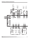
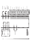
NOTE
The system control panel is furnished with pre-
wired circuits that can be interfaced/interlocked
with a make-up air unit, remote start/stop, remote
enunciator panel, fire suppression system, and/or
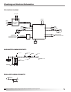
damper control. Please refer to the plumbing and
electrical schematics section for details on wiring
these components.
Figure 4
Strip 3/4 inch insulation
from cable
Fold wire down and back
Lay wire in terminal and
clamp tightly
Slide silicone boot over
terminal