


6
Grease Grabber™ Power Play Kitchen Exhaust Pollution Control System
Electrical
Once all system components are installed plumbing
connections for the system can be made. It is
recommended that plumbing connections be done
prior to making electrical connections.
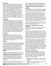
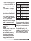
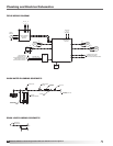
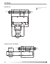
Electrostatic Cell Wiring
Using the supplied red high voltage cable in a
dedicated conduit line, connect the terminal point of
the ionizer portion of the cells to the Ionizer terminal in
the system power pack. Using the supplied blue high
voltage cable in a separate dedicated conduit line,
connect the terminal point of the collector portion of
the cells to the collector terminal in the system power
pack (See FIGURE 1).
CAUTION
RISK OF ELECTRIC SHOCK. All wiring to be done
by qualified personnel only.
NOTE
All wiring must be done according to the equipment
data plate information, NEC (National Electrical Code
NFPA 70), and local codes.
NOTE
All wiring must be permanently installed in conduit.
Under no circumstances should extension cords be
used to connect the source of electrical supply to
the equipment.
NOTE
The system control panel, power pack, and cabinet
assembly housing to a structural steel or earth
ground. The detergent pump motor and solenoid
valve must also be appropriately grounded.
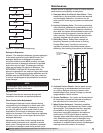
Knockout locations for conduit connections to carry
the high voltage cables are located at the top and
side of the system power pack and the sides of the
terminal box on top of the cabinet assembly. Use a
knockout punch to open holes for minimum 1/2-inch
conduit. Use caution to keep the system power pack
and terminal box interiors free of scraps and other
debris.
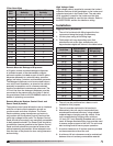
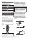
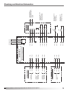
Once conduit is in place and high voltage cable has
been run, terminate the high voltage cables at the
power pack by stripping approximately 3/8-inch
of insulation from each wire and attach a supplied
terminal ring to each. Securely attach the terminal
ring end of the red cable to the Ionizer terminal in
the power pack and the terminal ring end of the
blue cable to the collector terminal in the power
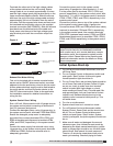
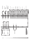
pack (See FIGURE 2). After the connections are
made, completely coat the terminal connection with
minimum 1/4-inch thick layer of silicone caulk (See
FIGURE 3).
NOTE
50 feet of each the red and blue high voltage cable
are provided with the unit. Under no circumstances
should the high voltage cable be spliced or
terminated at locations other than the specified
terminal points. If longer lengths of high voltage
cable are required for installation, consult the
manufacturer.
NOTE
Do not connect the ends of the high voltage cable to
the terminal points until all conduits are installed and
the high voltage cable is run.
AIR
FLOW
AIR
FLOW
AIR
FLOW
Figure 1
Red high voltage cable
from Power Pack
Blue high voltage cable
from Power Pack
Airflow
Figure 3
Silicone
caulk
Cable must pass
through clamp
Figure 2
Ring
terminal
Conduit with
bushing
Collector
Red
Ionizer
Blue