


16
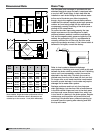
Model PVe Heat Recovery Unit
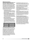
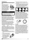
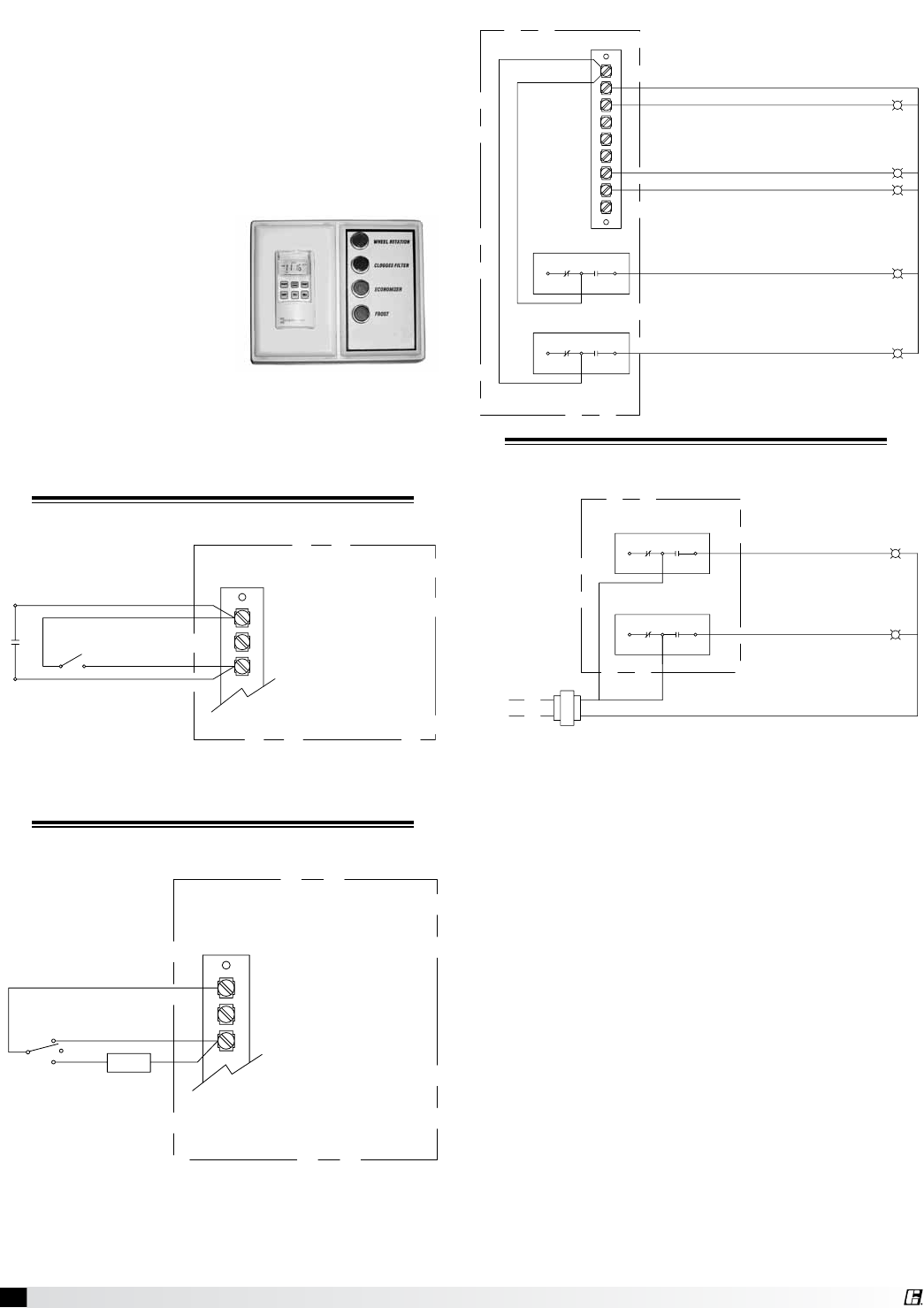
Remote Control Panel and Wiring
Schematics
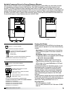
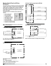
Indicator Lights powered by the ER Unit
Dirty Filter Indicator (power by others)
Refer to Pressure Switch for voltage and load ratings.
7-Day Timer or On/Off Switch
G
C
R
7-Day Timer
S1 - Unit On/Off
Terminal Block
in Unit
Control Center
For 7-Day Timer, use blue and black wires.
Red wires should be capped off.
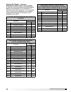
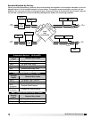
G
C
R
On
Off
BMS
Auto
Terminal Block
in unit
Control Center
Hand/Off/Auto Switch
Hand/Off/Auto Switch allows the unit to
“Off” - off
“On” - Manual Operation
“Auto” - Unit is controlled by BMS, RTU, etc.
NOTE: RTU controllers are by others.
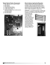
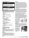
The remote panel is a series of junction boxes ganged
together and includes a stainless steel faceplate. The
remote panel is available with a number of different
alarm lights and switches to control the unit. The
remote panel ships loose and requires mounting and
wiring in the field
The remote panel is available with the following
options:
• Unit on/off switch
• Unit on/off light
• 7-day time clock
• Hand/off/auto switch
• Time delay override
• Economizer light
• Frost control light
• Exhaust air dirty filter light
• Outdoor air dirty filter light
Refer to Electrical Connections section for Field Control
Wiring recommendations.
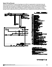
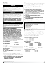
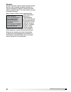
W1
12
7
6
Y2
Y1
G
C
R
NC
C
NC
C
NO
NO
Exhaust Dirty Filter
Supply Dirty Filter
Economizer
PS2
PS3
Frost Control
Unit On/Off
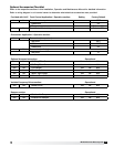
NC
NC
NO
C
NO
C
Exhaust Dirty Filter
Supply Dirty Filter
Hot
L1
PS2
PS3