


6
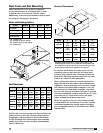
Model PVe Heat Recovery Unit
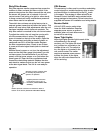
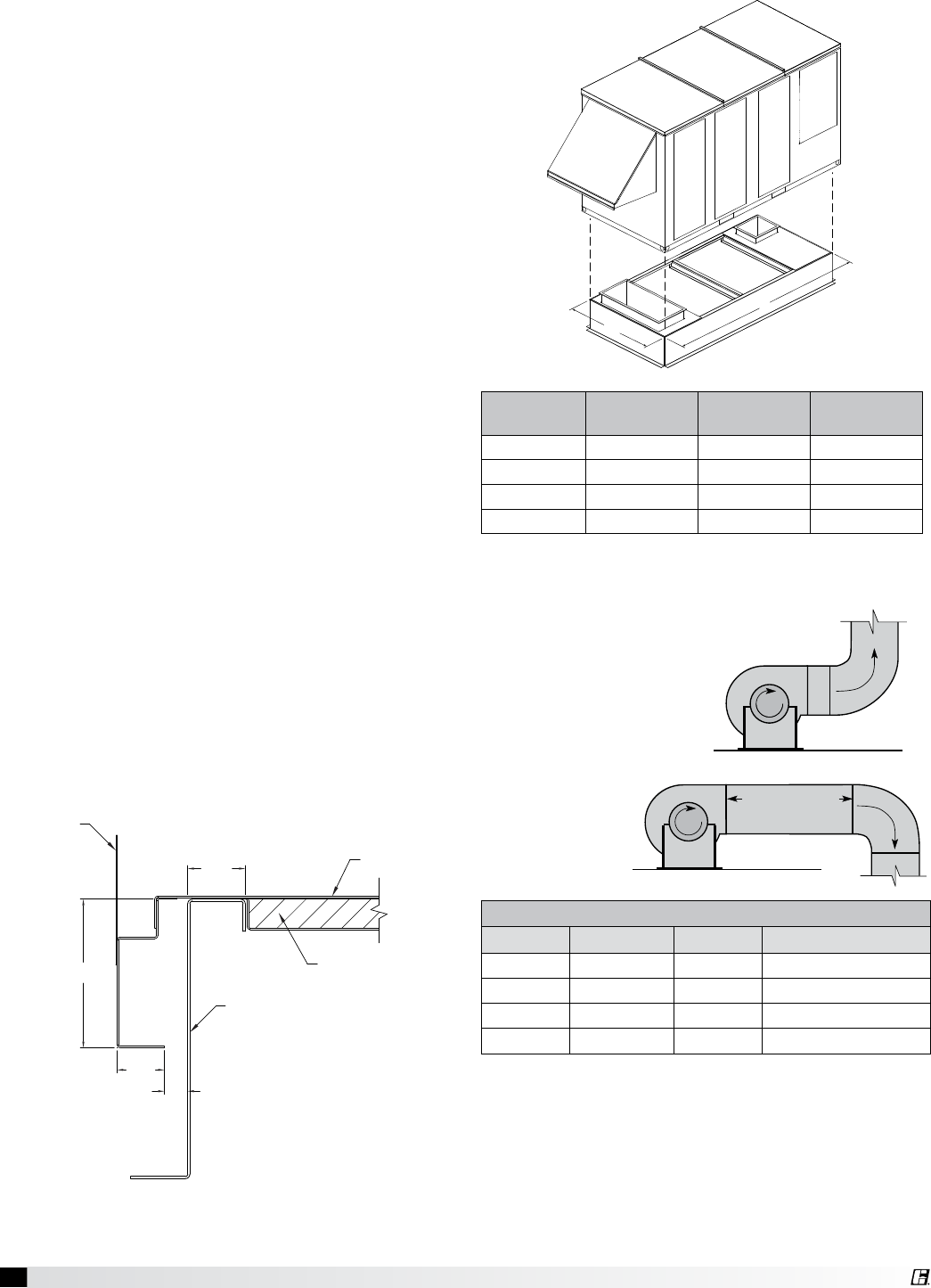
Roof Curb Mounting
Roof curb assembly and mounting instructions are
contained in the Roof Curb Assembly Instructions
supplied with Model GKD roof curb.
Rooftop PVe units require curbs to be mounted first,
in accordance with their appropriate instructions.
Curb unit is to be installed and then duct connections
are to be made prior to setting of the unit.
1. Factory Supplied Roof Curbs: Roof curbs are
Model GKD. The GKD ships in a knockdown kit
(which includes duct adapter) and requires field
assembly by others. Assembly instructions are
included with the GKD curbs.
2. Install Curb: Locate the assembled curb over
roof opening and verify precise location of curb
relative to the roof opening, in accordance with
dimensions given previously. Fasten curb loosely
in place and then shim as needed to ensure a
level installation. Tighten roof fastening hardware
and then re-check for level. Verify that diagonal
dimensions of installed curb are plus or minus
1/8-inch of each other.
3. Install Ductwork: Install needed ductwork in
accordance with SMACNA and AMCA guidelines.
Duct adapter is provided to support ducts prior
to setting the unit.
4. Install Insulation: One-inch deep insulation
pans are provided with the curb assembly. Set
the insulation pans per instructions and then
install insulation in the pans prior to setting
the unit. Insulation is not provided by the unit
manufacturer, it is to be supplied by others.
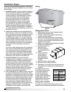
5. Set the PVe Unit: Lift unit to a point directly
above the curb and duct openings. Guide unit
carefully while lowering in order to align with duct
openings. The roof curb will seat in a recess in
the base of the PVe unit. Verify that the unit is
properly seated on the curb and is level.
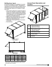
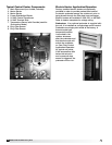
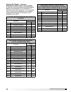
Unit Size L W
Curb Weight
(lbs.)
PVe-20 99.4 36.8 195
PVe-35 99.4 44.6 216
PVe-45 105.9 56.3 261
PVe-55 111.7 71.3 316
All dimensions are shown in inches.
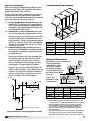
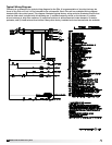
Curb Cap Details for Factory Supplied Roof Curbs
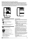
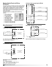
Ductwork Connections
Examples of poor and good fan-to-
duct connections are
shown below. Airflow
out of the fan should
be directed straight or
curve the same direction
as the fan wheel rotates.
Poor duct
installation will
result in low
airflow and other
system effects.
1 Fan
Wheel
Dia.
1 Fan
Wheel
Dia.
R
o
t
a
t
i
o
n
R
o
t
a
t
i
o
n
R
o
t
a
t
i
o
n
R
o
t
a
t
i
o
n
Length of Straight Duct
GOOD
POOR
GOODPOOR
GOOD
POOR
Turning
Vanes
Turning
Vanes
SYSTEM EFFECT FACTOR CURVES
FPM X 100
OUTLET VELOCITY
0 5 10 15 20 25 30 35 40 45
1.2
1.0
0.8
0.6
0.4
0.2
0.0
STATIC PRESSURE LOSS
CURVE 1
CURVE 2
CURVE 3
CURVE 4
L
W
Curb Dimensions and Weights
4.844
1.549
0.775
Insulation Pan
Unit Base
Roof Curb
Dimensions are shown in inches.
1.895
Unit Side
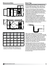
Recommended Discharge Duct Size and Length
Unit Size Blower Size Duct Size Straight Duct Length
PVe-20 9 14 x 14 36
PVe-35 10 20 x 20 36
PVe-45 12 20 x 20 36
PVe-55 15 28 x 28 60
All dimensions are shown in inches.
• Recommended duct sizes are based on velocities across the
cfm range of each model at approximately 800 feet per minute
(FPM) at minimum airflow and up to 1600 fpm at maximum
airflow. Recommended duct sizes are only intended to be a
guide and may not satisfy the requirements of the project.
Refer to plans for appropriate job specific duct size and/or
velocity limitations.
• Straight duct lengths were calculated based on 100% effective
duct length requirements as prescribed in AMCA Publication
201. Calculated values have been rounded up to nearest foot.
1 Fan
Wheel
Dia.
1 Fan
Wheel
Dia.
R
o
t
a
t
i
o
n
R
o
t
a
t
i
o
n
R
o
t
a
t
i
o
n
R
o
t
a
t
i
o
n
Length of Straight Duct
GOOD
POOR
GOODPOOR
GOOD
POOR
Turning
Vanes
Turning
Vanes
SYSTEM EFFECT FACTOR CURVES
FPM X 100
OUTLET VELOCITY
0 5 10 15 20 25 30 35 40 45
1.2
1.0
0.8
0.6
0.4
0.2
0.0
STATIC PRESSURE LOSS
CURVE 1
CURVE 2
CURVE 3
CURVE 4