


8
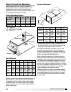
Model PVe Heat Recovery Unit
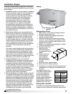
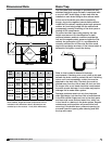
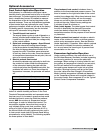
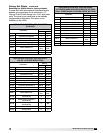
Dimensional Data Drain Trap
Unit
Size
A B C D E
PVe-20
104.1
(2650)
59.7
(1520)
41.5
(1060)
20.3
(520)
20.7
(530)
PVe-35
104.1
(2650)
59.7
(1520)
49.2
(1250)
25.2
(640)
17.7
(450)
PVe-45
110.6
(2810)
59.7
(1520)
61.1
(1560)
25.2
(640)
19.0
(490)
PVe-55
116.5
(2959)
59.7
(1520)
76.1
(1940)
25.2
(640)
23.8
(610)
All dimensions are shown in inches (millimeters).
Door handles, hinges and other protrusions are not
included in the dimensions above. Dimensions are
rounded up to the nearest .1 inch (2.54 millimeters).
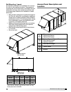
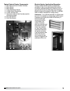
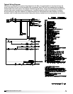
Bypass
Damper
Face
Damper
Outdoor Air Hood
Filters
Filters
Filters
Exhaust
Air Hood
Control Center
Face/Bypass Damper
Plate Heat
Exchanger
Plate Heat
Exchanger
Outdoor
Air Hood
C
B
AD
E
CLEARANCE
CLEARANCE
B
C
A
D
D
Top view
Bypass
Damper
Face
Damper
Outdoor Air Hood
Filters
Filters
Filters
Exhaust
Air Hood
Control Center
Face/Bypass Damper
Plate Heat
Exchanger
Plate Heat
Exchanger
Outdoor
Air Hood
C
B
AD
E
CLEARANCE
CLEARANCE
B
C
A
D
D
Side view
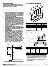
The PVe plate heat exchanger is provided with two
stainless steel drain pans and each is equipped with
a one inch MPT drain fitting. A drain trap must be
installed on each drain fitting to allow excess water
to flow out of the drain pans. More importantly,
though, due to the negative internal static pressure
inside the PVe cabinet, installing drain traps prevents
outdoor air from being pulled into the cabinet and
consequently causing overfilling of the drain pans or
misting of PVe components.
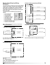
To ensure the drain trap works properly, the trap
height must account for the difference in static
pressure between ambient conditions outside the
unit and the negative static pressure inside the PVe
cabinet. An assumption of 3.0 in. wg differential is
normally sufficient for all PVe units and this would
require a trap design as shown. If the internal static is
believed to be higher, consult the factory.
Refer to local codes to determine drainage
requirements. If draining onto a roof, place a drip pad
beneath the drain outlet to protect the roof. If draining
onto a roof is not acceptable, a drain line must be
attached to the drain trap. The drain line must be
pitched away from the unit at least 1/8-inch per foot.
On longer runs, an air break should be incorporated
to ensure proper drainage. Local codes may require
drainage into a waste water system.
Drainage problems result not only from improper
drain trap design, but also from lack of maintenance
in the PVe cabinet. Algae can form in the drain pans
and traps and cause reduced water flow, which can
in turn result in a backup in the drain system. Regular
maintenance and inspection will prevent this from
occurring. If the drains have a cleanout opening, be
sure and close the opening after cleaning and refill
the trap with water.
4 in.
2 in.