


Page 6 Model LCD-2R and LCD-2A
Installation (cont.)
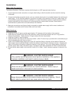
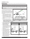
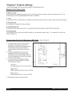
Electrical Hook-up: Ensure water connection is made to machine before proceeding and water source is
turned ON.
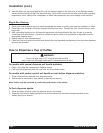
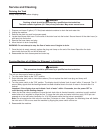
The electrical ratings for your dispenser are
located on the serial plate on the outside cabinet.
For configuration of heater to optional wattages,
refer to configuration decal 50524-04 located on
the inside surface of the electrical access panel.
(see Figure B)
1. For cord connected models, plug the power
cord into an appropriate grounded and
dedicated electrical outlet. Go to step 8.
2. For hard-wired models not supplied with an
electrical cord, the dispenser should be
connected to a dedicated circuit with a fused
disconnect switch or a circuit breaker near the
dispenser.
3. Strain relief knockouts are supplied on the
back of the machine chassis for power entry.
• Electrical connections and wiring
materials must conform to local codes and/or be in
compliance with the National Electric Code.
• Use only copper conductors
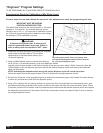
4. Remove the access panel located on
the lower right side of the dispenser.
Note: wiring diagram is on
backside of access panel.
5. Connect the power supply
conductors, neutral and ground wire
to the appropriate positions on the
terminal block located on the lower
right side of the dispenser. The
ground lug is separate from the
terminal block.
6. Install the side access panel.
7. Flip power supply to machine “ON”
at the branch supply disconnect.
8. Flip power switch to the “ON”
position and allow the water tank to
fill. The LCD display on the front
door should indicate “FILLING”.
NOTE: Power switch is located at
the right lower rear corner of
machine. The machine will make a
subtle hissing sound while filling.
Allow 3-4 minutes for fill time
depending on water pressure.
NOTE: Installation must be performed by a qualified electrician and must conform to all local and national codes.
!
"
!
"
!
"
"#$!
#"$!
%"&' (
Figure B
! "#$"$%&'()"%*+*%,
-.$/0.*"-&12".+*%0"-2$*"-
3 0&14.$0"-+*5/$.*"-
!
"#$%
&'
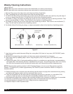
NOTE: Machine is factory configured for field wiring and power cord is not provided. If the machine is intended
to configured to 120 volt operation, a conversion kit 63578 is available for the addition of a proper 120 volt power
cord and a serial tag conversion procedure to match the serial tag to the 120 volt wattage of the heater.
(Refer to Figure A).
Figure A