


Crathco
®
Post Mix Beverage Dispensers l Page 9
into clean container. (see figure H)
2. Close the cabinet door and dispense the warm water the same way, as it would be a product. Dispensing
should last for no longer than 90 seconds.
3. Repeat the above for all remaining dispensing stations.
Washing Parts
Proceed as described in “Wash Parts” without flushing.
Sanitizing
Prepare sanitizing solution per instruction on the package changing the strength of the solution to be equivalent to
6+1 e.g. If instruction calls to dilute contents of the sanitizer package in 4 liters of water use only 0.6 liters of the
water for the solution. Fill the clean container that was used for tubing cleaning with the sanitizing solution.
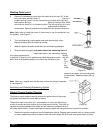
1. Install container with sanitizer solution in the cabinet and connect pump tubing to product pick up tube assembly.
2. Close the cabinet door and depress dispensing switch corresponding with position of the container with
sanitizing solution for 15 seconds.
3. Wait 3 minutes.
4. Lift the pick up tubes assembly to be above the sanitizing solution and depress the same dispensing switch
for 2 seconds to avoid sanitizer spillage inside of the cabinet. Rinse the pick up tube assembly and connect it
back to the pump tubing.
5. Replace the container containing the sanitizing solution with the product container.
6. Depress dispensing switch. Keep dispensing product until 200 ml is dispensed with correct brix.
7. Repeat steps 1 to 6 for all remaining stations.
8. Turn the flush switch to FLUSH and depress each dispensing switch for 4 seconds.
Note: Do not skip any sanitizing procedure step.
Flushing
Proceed as described in Flushing the Dispensing System. Flushing
time is only 4 seconds.
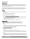
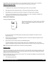
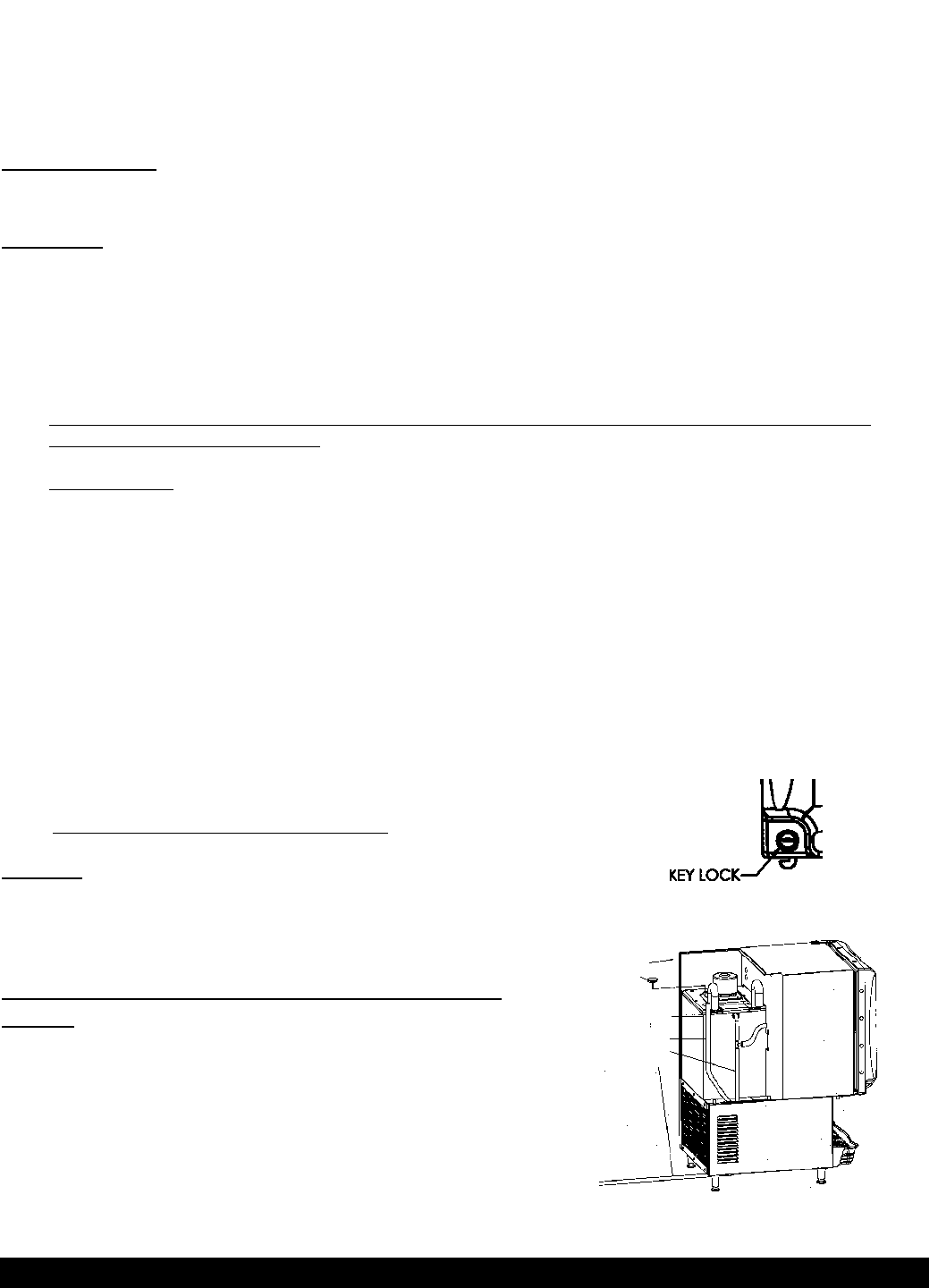
Preventing Unauthorized Dispensing During “Off
Hours”
After system flushing, do not turn the flush switch to the DISPENSE
position. Lock the door and remove the key from the lock. This will
allow dispensing cold water only. (See figure I)
Note: Turn the flush switch to DISPENSE when resuming operation
the next day.
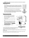
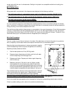
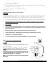
Overflow
Drain
Water Level
Gauge
Air In
Water Level 1.5
cm below top
cover
Back of unit
Ice Tank Plug
›
›
›
›
›
›
Air Out
(Figure I)
(Figure J)