


6
OVLERQ*C OVLSRQ*C OVLESRQ*F OVLSERQ*F
97793C - 10/01
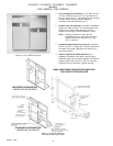
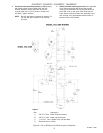
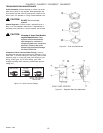
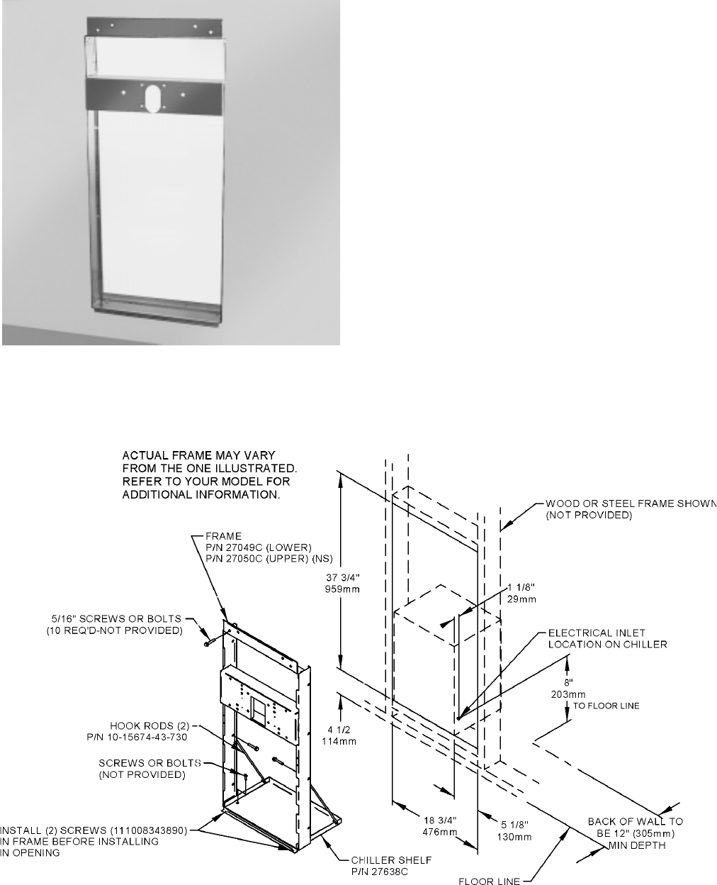
Figure 9 OVL-II ER-Q/OVL-II SR-Q Rough-In
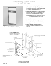
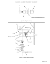
Figure 10 Rough-In Assembly
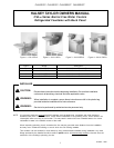
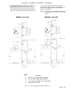
Single-Station Mounting Frames
Models
OVL-II ER-Q OVL-II SR-Q
1. Cut a rectangular wall opening 18-3/4
(475 mm) W x 37-3/4 H (959 mm) and 4-1/2 (114 mm)
above the floor line (see Figure 10). The dimensions
are required to obtain proper rim and bubbler heights
for compliance with ANSI standard A117.1.
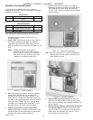
2. Reinforce the wall opening on all sides to adequately
support the water fountain. This reinforcement must
support up to 150 lbs. static load and provide a
means for securing the frame assembly in place.
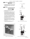
NOTE: Building construction must allow for adequate
air flow on both sides and top of remote
chiller unit. Minimum of 4 (102 mm) is
required.
3. Install plumbing and electrical rough-ins. A junction
box for a (3) wire, 10 amp branch circuit is provided on
the inside of the chiller. (Standard 120 Volts, 60 Hz,
and single phase.)
4. Remove frame and related hardware from
packaging. Release the two shelf rods by cutting
cable ties.