


12-02 13 34615 Rev G
NOVUS B-VENT INSTALLATION INSTRUCTIONS
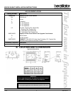
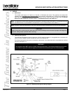
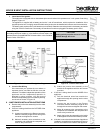
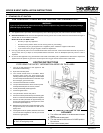
c. Intermittent Pilot Ignition
This appliance is equipped with an intermittent pilot control valve which operates on a 3 volt system. See wiring
diagram, Figure 15.
The appliance is supplied with a battery pack and a 3 volt AC transformer, which requires the installation of the
supplied junction box. It is highly recommended that the junction box be installed at this time to avoid reconstruction.
The battery pack requires two D cell batteries (not included). Batteries cannot be placed in the battery pack while
using the 3 volt AC transformer. Conversely, the transformer must be unplugged if the battery pack is used.
Figure 15 - Intermittent Pilot Ignition Diagram
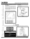
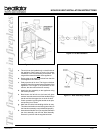
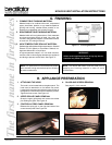
Figure 16 - Junction Box Detail
d. Junction Box Wiring
We recommend you operate the two outlets on
separate circuits, one side hot full time, one side
switched. This allows independent operation of the
appliance and fan. Independent operation is
obtained by using minimum 14-3 with ground
Romex and separating the two outlets by breking
out the tab as shown in Figure 16.
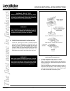
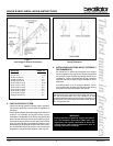
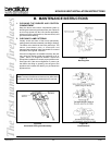
6. JUNCTION BOX INSTALLATION INSTRUCTIONS
a. Remove the junction box assembly from the valve
compartment.
b. If the box is being wired from the OUTSIDE of the
appliance:
1) Loosen two screws on the Romex connector,
feed the necessary length of wire through the
connector and tighten the screws.
2) Make all necessary wire connections to the
receptacle and assemble the receptacle and
cover to the junction box.
Note: This appliance must be electrically wired and grounded in
accordance with local codes or, in the absence of local codes, with
National Electric Code ANSI/NFPA 70-latest edition or the Canadian
Electric Code, CSA C221.1.
CAUTION:
Battery polarity must be correct or control
module damage will occur.
3) Attach the junction box assembly to the
outside of the appliance with the two screws
provided.
c. If the box is being wired from the INSIDE of the
appliance:
1) Pull the electrical wires from outside the
appliance through this opening into the valve
compartment.
2) Loosen the two screws on the Romex
connector, feed the necessary length of wire
through the connector and tighten the screws.
3) Make all necessary wire connections to the
receptacle and assemble the receptacle and
cover to the junction box.
4) Attach the junction box assembly to the inside
of the appliance with the two screws provided.
d. If the box is not to be wired at the time of appliance
installation, assemble the receptacle and cover to
the box and install on the inside of the appliance.