


4
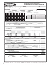
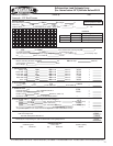
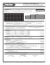
Job Survey
The person involved in a heat transfer calculation needs
information in order to predict accurately the heat load on a
refrigerated structure. The more complete the information, the
better the calculation. Good calculations are the rst step in
assuring adequate refrigeration equipment is selected for the
project.
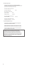
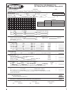
The initial job survey should be as complete as possible and
include the following:
Design Ambient Temperature
This is the ambient surrounding the box necessary for the load
calculations. Another ambient to be considered on air cooled
projects is the one surrounding the condensing unit which will
aect equipment selection.
Storage Temperature and Humidity Requirements
Refrigeration equipment by its nature is a dehumidication
process. We try to minimize or maximize the drying eect of the
equipment by selecting the appropriate Temperature Dierence
(T.D.) between the saturated suction temperature of the
evaporator and the room air. The T.D. selected approximates the
desired relative humidity (see page 21).
Dimensions, Insulation, Type of Construction,
Exposure
This criterion lends itself to well established, straight forward
calculations, but the information while elementary, is often
omitted from the initial job survey. Transmission load for 4”
Styrofoam is double the transmission load for 4” formed in place
urethane.
Inltration or Air Changed Load
Heat, both sensible and latent, enters an enclosure through door
openings whenever the air surrounding the enclosure is warmer
than the box temperature. Knowing the location, size and
number of the door openings and the temperature to which they
are exposed will greatly aid in determining the heat load of the
inltration air.
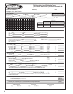
Product
1. Type - storage requirements
2. Weight
3. Entering temperature
4. Pull down time
Miscellaneous Loads
1. Lights
2. Motors including fan motors, fork lifts, conveyers
3. People
4. Glass doors
Operations
1. Holding cooler or freezer
2. Blast cooling or freezing
3. Preparation, processing or cutting rooms
4. Distribution warehouses
5. Reach-in or walk-in boxes
Unusual Conditions
Electrical Service and Type of Equipment Desired
While not directly aecting refrigeration load calculations,
this is essential in the job survey to select the proper equipment.
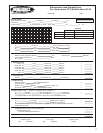
Refrigeration Load Calculations
With the initial survey complete, the heat load calculation is
separated into the following main sources of heat for a given 24
hour period:
1. Transmission load
2. Air change load
3. Miscellaneous load
4. Product load
Accuracy
Accuracy in calculation is the rst step in having a satised
customer. There are short cuts, based on averages, that may
be taken and which must be used when the product load is
indenite or unknown (see Quick Selection Guide on page 41
and the Rapid Load Calculator on page 43). But when all the data
necessary to calculate the four main sources of heat gain are
available, the complete calculation should be made.
Quick Selection Chart for Small
and Medium Coolers and Freezers
The Quick Selection Guide on page 41 may be used for a quick
comparison of heat load gured on Bulletins Above32-05 or
Below32-05 or to obtain approximate heat loads for small and
medium sized boxes. The loads are shown for a 95ºF. outside
temperature.
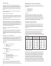
Rapid Load Calculator for Large Coolers and Freezers
The Rapid Load Calculator on page 43 may be used for quick
approximations of the heat load in large boxes and for a
reasonable comparison of heat loads gured on Bulletins
Above32-05 or Below32-05. The Calculator graph on page 43 is
based on the following average daily product loadings for coolers
and freezers:
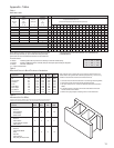
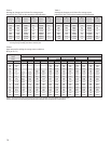
1. Transmission Load
Methods of determining the amount of heat ow through walls,
oor and ceiling are well established. This heat gain is directly
proportional to the Temperature Dierence (T.D.) between the
two sides of the wall. The type and thickness of insulation used
in the wall construction, the outside area of the wall and the
T.D. between the two sides of the wall are the three factors
that establish the wall load. Tables are provided to simplify
the calculations (see Table 1, page 13). Some coolers for above
freezing temperatures have been constructed with only a oor
slab (no oor insulation). The factors shown in the wall heat gain
(Table 1) are based on a concrete oor slab and the T.D. between
the local ground temperature and the storage room temperature.
Average Daily Average Daily
Volume- Product Loads (lbs.) Product Loads (lbs.)
Cu. Ft. for Coolers for Freezers
500 - 3,000 6,200 - 8,000 1,600 - 2,000
3,000 - 4,600 8,000 - 11,000 2,000 - 2,500
4,600 - 8,100 11,000 - 17,000 2,500 - 4,000
8,100 - 12,800 17,000 - 26,000 4,000 - 6,200
12,800 - 16,000 26,000 - 33,000 6,200 - 7,500
16,000 - 20,000 33,000 - 40,000 7,500 - 9,500
20,000 - 28,000 40,000 - 56,000 9,500 - 13,000
28,000 - 40,000 56,000 - 66,000 13,000 - 17,000
40,000 - 60,000 66,000 - 110,000 17,000 - 25,000
60,000 - 80,000 110,000 - 150,000 25,000 - 34,000
80,000 - up 150,000 - up 34,000 - up