


20
CheckingOperationOfExpansion
Valve(EEV)
To check if the expansion valve is closing properly:
Install a pressure gauge-set to suction line at
the condensing unit. With the system running,
close the valve on the liquid line, at the con
densing unit. The system should pumpdown
and shut off on the Low Pressure switch (LPS).
If the system does not pumpdown and trip on
the LPS then the compressor valves are weak
and needs to be changed.
After the system pumps-down and trip on the
LPS, put the system in the service mode. This
will cause the Expansion valve to close. Open
the valve on the liquid line, at the condensing
unit. The suction pressure reading on the gauge
set should not increase. If the suction pressure
increases then the expansion valve is leaking
and should be changed.
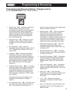
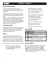
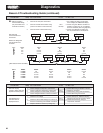
CheckingOperationofExpansionValve
If the expansion valve is suspected of not functioning
properly the motor windings resistance should be
measured. This is a bipolar motor with two windings.
Measure the resistance at the pins, on top of the valve,
between locations A and B
or C and D.
Expansion Valve
Motor Winding
Pins
The Expansion valve position can be monitored from
the LED display pressing the “MONITOR” button and
scrolling to ESP. This will indicate the number of steps
the valve is open.
This can also be checked by using the EXV test pins on
the board. This is indicated by a 0 to 5 Volts DC signal.
At 0 Volt the valve is closed and at 5 Volts the valve is
fully open. At values between 0 and 5 Volt, the valve will
be opened proportionately.
Use the “MONITOR” button to display “SCP””
Evaporator Suction Pressure. Record the pressure
displayed. Start the system and observe the pressure
displayed. If the pressure does not increase, the
expansion valve could be defective.
If the system is running, use the “MONITOR” button to
display “SCP” Evaporator Suction Pressure. Record the
pressure displayed. While the system is running, press
the “FORCESERVICE” button. Observe the pressure
while the system is pumping down. The pressure should
decrease. If it does not, this indicates a defective valve.
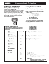
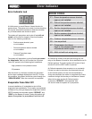
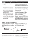
ExpansionValveMotorWindingResistance
A• •C
• •
B D
(Note that the pins are not labeled A, B, C, D. This
labeling is just for reference. Also, two of the pins, at
location B and location D, have a wider spacing between
them than between location A and C)
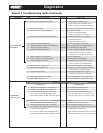
For valve size 29320003 and 2930004, the resistance
measured between pin locations A and B or C and D
should be approximately 336 Ohms when valve is at
75ºF.
For valve size 2930007, 29320008, 29320013 and
29320014, the resistance measured between pin
locations A and B or C and D should be approximately
116 Ohms when the valve is at 75ºF.
Continues to Page 21