


5
The electric expansion valve and the suction temperature
sensor on the suction line are factory installed.
Care must be taken when brazing these lines at the
evaporator.
Toohighatemperaturemaydestroythese
components.Heatabsorbingcompoundsor“wet
rags”mustbeusedtoprotecttheelectricexpansion
valvewhenbrazingtherefrigerantlineconnections.
Thesuctionlinesensorshouldberemovedbefore
brazing.
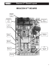
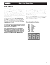
PowerSupply
The Beacon II board gets its 24 VAC power supply from
a transformer mounted in the electrical end of each
evaporator. On 208-240 volt systems the multi-tap
transformer is shipped from our factory wired for 240
volts. If your supply voltage is 208 volt you must change
to the 208 volt tap on the transformer.
VERYIMPORTANT: If the supply voltage to the
evaporator is 208 volts, the primary tap of the
transformer must be moved to the 208 volt tap.
Thismustbedoneforalltheevaporatorsonthat
system.
If the 24 VAC power supply falls below 18 VAC the
system may power down and shut off. When the power
supply is corrected to 24 VAC the system will restart
after the four minute hold-off period and resume normal
operation.
On Beacon II systems the main power for the evaporator
can be supplied separately from the power supply of the
condensing unit. All wiring, however, must comply with
local electrical codes.
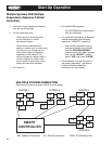
Wiring
Wiring between the condensing unit and the unit
cooler(s) will be as follows (see wiring diagrams):
• High voltage - There may be high voltage on
the defrost heater relay and the fan relay.
The evaporator may also be connected to a
separate power supply from the condensing
unit. See unit cooler spec. plate for ampacity.
Brazing
• Low voltage - 24V Class II control circuit.
A total of ve low voltage leads are required
to connect the condensing unit to the
evaporator. (See wiring diagram.) Two of
these leads are for connecting the outdoor
temperature sensor. The other three leads
are for connecting the compressor relay,
service relay and 24V Common inputs.
All24voltwiringmustberunseparate
fromthelinevoltagewiring.
• Low voltage wiring must be 18 gauge
minimum. For low voltage wiring, maximum
distances are:
Condensing unit to Master evaporator 500 ft.
Between evaporators 500 ft.
Smart Controller to Master evaporator 1000 ft.
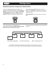
• Multiple units – The multi-in and multi-out
are the communication connections.
Connection sequence must follow the multi-
out terminal to the multi-in terminal and
the multi-out back to the multi-in terminal in
a daisy chain loop.
• Alarm circuit - The onboard alarm is a
dry set of NC contacts which closes to
indicate an alarm. The type and wiring for
the alarm is customer specied. Note that
the alarm circuit does not distinguish or
indicate what has caused the alarm.
• All wiring must comply with all applicable
codes and ordinances.
RefrigerantLineBrazing(Caution)