


5
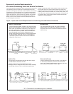
Suction Filters, Driers, Sight Glasses
There are two types of suction and liquid filter/driers used
on Heatcraft Refrigeration Products units. Replaceable core
and/or sealed units are used, dependent upon the option
package ordered.
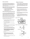
Suction filters, regardless of type, are always installed
upstream of the compressor suction service valve, and
any accumulators or other options that may be installed.
Suction filters are equipped with “Schrader” type access
valves to allow field measurement of pressure drop across
the device. This allows plugged filters and elements to be
identified very quickly and easily so they can be replaced
when the pressure drop is excessive. Refer to the specific
manufacturersʼ recommendation on servicing these units by
make and model.
Liquid filter/driers, regardless of type, are always installed
downstream of the receiver outlet service valve, and up-
Condensing Unit Accessories
stream of the liquid line solenoid valve (if supplied). Liquid line
driers may or may not have an access valve, dependent on the
size and application. The basic servicing of these units is similar
to suction filters. Liquid line driers should be replaced whenever
there is evidence of excessive pressure drop across the filter,
or the system becomes contaminated due to system leaks,
compressor burnouts, acid formation, or moisture accumulation
as indicated by the liquid line sight glass.
The sight glass is installed in the main liquid line assembly,
downstream from the receiver outlet service valve, and
immediately after the liquid line drier. The sight glass is
designed to give a visual indication of moisture content in the
system. Generally, it requires no field service. However, in
cases of extreme acid formation in a system after a compressor
burnout, the acid may damage the sensing element or etch the
glass. This would require that the sight glass be replaced, along
with the liquid line drier after any compressor motor burnout.
CAUTION: Fans closest to the headers should not be
cycled on standard temperature or pressure
controls. Dramatic temperature and pressure
changes at the headers as a result of fan action
can result in possible tube failure. Fan motors are
designed for continuous duty operation.
Fan cycling controls should be adjusted to maintain a minimum
of (5) minutes on and (5) minutes off. Short cycling of fans may
result in a premature failure of motor and/or fan blade.
Compressors operating below +10°F SST must have air flowing
over the compressor at all times when the compressor is
running.
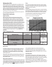
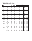
Design Thermostat Settings
Models T.D. T1 T2 T3
30 60
2-fan units: 25 65
20 70
4-fan units: 15 75
30 60 40
3-fan units: 25 65 55
20 70 60
6-fan units: 15 75 65
30 60 50 30
8-fan units: 25 65 55 40
20 70 65 50
15 75 70 60
NOTE: Cycle pairs of fans on double wide units.
Table 2. Thermostat Settings
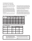
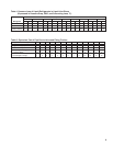
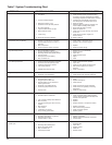
Table 1. Recommended Low Pressure Control Settings for Outdoor Air Cooled Condensing Units
R-22 R-404A/R-507 R-134a
*Minimum Cut-In Cut-Out Cut-In Cut-Out Cut-In Cut-Out
Temp. ˚F PSI PSI PSI PSI PSI PSI
50 70 20 90 35 45 15
40 55 20 70 35 35 10
30 40 20 55 35 25 10
10 30 10 45 25 13 0
0 15 0 25 7 8 0
-10 15 0 20 1 --- ---
-20 10 0 12 1 --- ---
-30 6 0 8 1"Hg. --- ---
* Minimum ambient or box temperature anticipated, Hi pressure control setting: R-22, 360 PSI; R-404A, R-507, 400 PSI; R-134a, 225 PSI.