


2-40 HP Portable Chillers Chapter 3: Installation 21 of 78
System Configuration. The system can be configured in any of the arrangements shown on
page 62 of the Appendix. The configuration and distance between the chiller and the
condenser affects pipe size, refrigerant charge, oil return, and oil charge. Therefore there are
limitations that must be adhered to for reliable and optimal operation.
• Leaving water temperature affects discharge line size. Be sure to inform the installing
contractor of the leaving water temperature range in which the chiller will be operating
• The total distance between the chiller and condenser must not exceed 200 feet or 300
equivalent pipe feet
• Discharge line risers cannot exceed an elevation difference greater than 100 feet
without a 2% efficiency decrease.
• Refer to page 62 of the Appendix for the location of traps.
• Refrigeration lines must not be crossed, i.e., chiller liquid lines are to be piped to
condenser liquid lines.
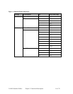
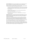
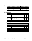
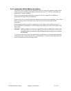
Sizing Refrigerant Lines. To determine field installed liquid and discharge line sizes, first
establish the equivalent length of pipe for each line, valve, and elbow. Chiller capacity and
leaving water temperature range is also required. See Figure 2 on page 22 for lengths of
refrigerant valves and fittings.
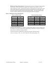
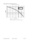
Liquid Line Sizing. The liquid line should be sized as small as possible while maintaining
acceptable pressure drop to minimize the refrigerant charge. Liquid line risers must not
exceed 15 feet from the base of the air-cooled condenser. Horizontal runs do not require a
pitch. Insulation is not required unless the line is installed in a high ambient area, i.e., boiler
room. Install a liquid line-charging valve to facilitate refrigerant charging. See Figure 3 on
page 22 for sizing information. See Figure 5 on page 23 for charge determination.
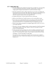
Discharge Line Sizing. For horizontal runs, the discharge line should be pitched downward,
in the direction of flow, at a rate of 1/2” for every 10 feet. This will allow oil to flow towards
the condenser. Discharge line sizing is based on the velocity required for sufficient oil return
back to the compressor. See Figure 4 on page 22 for discharge line sizing.