


IMPORTANT!
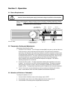
Chillers equipped with a high pressure positive displacement pump have a pressure
regulator inside of the chiller and a pressure gauge on the control panel. To access this
regulator, remove the rear air grille. The valve is located to the right. On models 6107 & 6705,
6155 the regulator is located center point, upper grille (rear).
The Pressure Valve is FACTORY ADJUSTED to 40psi. If you do NOT want to operate at this
pressure, or do not know what your operating pressure should be, start at a lower operating
pressure. Reduce the pressure by turning the valve counterclockwise (unscrew outward)
before starting the chiller.
With the chiller fully connected and running, read the pressure gauge and turn the regulator
to the desired pressure. If required, an optional external pressure reducing assembly is
available for this pump to reduce the pressure to 10 - 45 psi.
2.4 Setting Up a Closed System or Cooling Coil to the Chiller
1. Connect your closed cooling system to the chiller with hoses or pipes. The direction of the flow
through the system can be controlled by the way the hoses or pipes are connected to the chiller.
The “Inlet” will draw liquid into the chiller; the “Outlet” will pump liquid out.
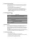
2. Turn the access panel screws to remove the top cover and expose the reservoir. Turn the filler
cap and lift up to remove. Use a funnel to fill the reservoir with fluid. When full, remove the
funnel, but do not replace the cap at this time. Check hoses and fittings for tightness and be
sure there are no bends or crimps in the hoses.
3. Plug the chiller into the proper AC outlet (unit's electrical requirements on rear of unit). Press
the POWER ON button. The chiller will begin pumping liquid through your system. Check for
leaks.
4. With the pump running, the reservoir's fluid level will decrease as the closed system begins to fill.
Add a little fluid at a time until the level in the reservoir stops going down. This means that your
system is filled and the air has been purged from it. Replace the reservoir cap and turn it
clockwise to lock it. Recheck the cap for tightness.
Note: When chillers with the standard magnetic drive centrifugal pump are connected to an external
apparatus with a built-in flow shut-off, an external bypass loop assembly (pt.# 510-147) may be
needed if operating below 20°C. This bypass assembly continues fluid circulation to and from the
pump even though the main flow to the external apparatus has been blocked.
2.5 Setting Up an Open Bath System to the Chiller
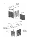
1. Connect hoses to the Inlet and Outlet fittings on the back of the chiller. The "Inlet" draws fluid
into the chiller, the "Outlet" pumps fluid out. Fill the open bath. Considering this flow, position
the hoses in your bath for a good circular flow and stirring motion.
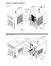
2. Turn the panel screws to remove the top cover and access the reservoir. Turn and lift the filler
cap to remove. Use a funnel to fill the reservoir with the same fluid in your bath. This primes the
pump and helps establish a flow when the chiller is turned on.
3. Replace the reservoir cap and turn to lock it. Check for tightness. Check all hoses and fittings.
Be sure there are no bends or crimps in the hoses, and that the hose attached to the chiller's
inlet is submerged near the bottom of the bath. Secure the inlet and outlet hoses to the open
tank so they do not move when pumping starts. The bath's fluid level will drop slightly as the
hoses in the system fill up with fluid. The bath's fluid must cover the chiller's inlet hose.
4. Plug the unit into the proper AC outlet (unit's electrical requirements on rear of unit). Press the
Power On button. The chiller will begin pumping fluid through your system. Check for leaks.
8