


– 5 –
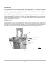
CARRIAGE (Model 5212)
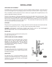
In use, the carriage can roll back and forth between the left carriage stop (Fig. 4) and the right carriage
stop, assuming the spring loaded carriage lock (Fig. 5) has not locked the carriage in a stationary
position.
To remove the carriage, turn either of the carriage stops 90 degrees so the bumper is toward the rear
(Fig. 4). Roll the carriage off either end while lifting it free of the carriage guide (Fig. 5).
To reinstall the carriage, hold the carriage so the center bearings (underneath) are aligned with the
carriage guide. Roll the carriage into place. Return the carriage stops so the carriage is stopped at
both ends.
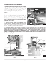
REMOVING THE BLADE
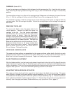
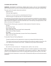
To remove the blade, raise the gauge plate to its
vertical position. Remove the table and move the
carriage to the left. Turn the tension adjustment
handwheel (Fig. 6) to the left to lower the upper pulley
(release tension on blade). Open the head door.
Swing up nylon guard on lower wiper assembly (Fig. 3)
and remove the saw blade. Lower the upper guide and
guard assembly to its lowest position. Reinstall the
blade so the teeth point to the right and down (Fig. 2).
Adjust the blade tension to its proper setting (see
B
LADE TENSION ADJUSTMENT, below). Check the blade
back-up blocks (see A
DJUSTING THE BLADE BACK-UP
BLOCKS, below). Reinstall the table.
Fig. 6
UPPER AND LOWER PULLEYS
The upper and lower pulleys are assembled on the upper and lower pulley shafts; the latch on each
pulley should be seated in the groove of the pulley shaft (Fig. 4). Pulleys can be removed after the
blade has first been loosened and removed. Upper and lower pulleys are interchangeable.
BLADE TENSION ADJUSTMENT
With the blade installed, turn the tension adjustment hand wheel to the right until the figure 3 starts to
show in the tension indicator (Fig. 6). Rotate the upper pulley a few turns by hand until the blade centers
itself on the pulleys. Then turn the tension adjustment hand wheel slowly to the right until the indicator
registers 4 at eye level. This is the maximum operating tension for the blade.
ADJUSTING THE BLADE BACK-UP BLOCKS
The upper and lower back-up blocks support the back edge of the blade during sawing. The upper
back-up block is located in the upper guide and guard assembly (Fig. 6); and, the lower back-up block
is located below the blade guide on the lower guide and wiper assembly (Fig. 3). Clearance between
back-up blocks and blade should be approximately
1
/32". Adjust to this dimension by turning adjustment
screw(s) after changing saw blades; blade widths may vary (see B
LADE GUIDE, page 6).
PL-40789-1
Tension Indicator
Knob
Upper Guide and Guard
Upper Back-up Block
Tension Adjustment Hand Wheel
Upper Pulley Wiper Hand Knob