


– 10 –
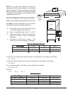
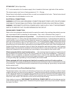
STEAM HEAT (When Specified)
A
3
/4" union connection for the steam supply line is located at the lower right side of the machine.
The steam supply must have a flowing pressure of 15 – 20 psig.
Steam flow is controlled by a solenoid valve, as well as a mechanical ball valve. The ball valve should
be closed when the dishwasher is not in use.
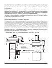
ELECTRICAL CONNECTIONS
WARNING: ELECTRICAL AND GROUNDING CONNECTIONS MUST COMPLY WITH THE APPLICABLE
PORTIONS OF THE NATIONAL ELECTRICAL CODE AND/OR OTHER LOCAL ELECTRICAL CODES.
WARNING: DISCONNECT ELECTRICAL POWER SUPPLY AND PLACE A TAG AT THE DISCONNECT
SWITCH TO INDICATE THAT YOU ARE WORKING ON THE CIRCUIT.
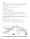
DISHWASHER CONNECTION
Refer to the wiring diagram attached inside the control box and to the machine data plate for service
size requirements when connecting the dishwasher. Also, refer to Electrical Data, page 12.
When circuit breaker option is not provided . . . the dishwasher electrical service connections are
made through the 1
3
⁄4" hole in the right-hand bottom of the control box. A fused disconnect switch or
circuit breaker must be installed in the electrical service line supplying this dishwasher and should
meet the requirements of your local electrical code. The incoming power supply connections should
be made to the terminal block in the control box and a ground lead should be connected to the
grounding lug in the control box if grounding is not provided by the conduit used. When equipped with
single point electrical connection option for both the dishwasher and electric booster, one incoming
electric supply line should be connected to the terminal block in the control box and a ground lead
should be connected to the grounding lug if grounding is not provided by the conduit used.
When equipped with the circuit breaker option . . . the incoming electrical supply or supplies should
be connected to the terminal block in the circuit breaker box on top of the dishwasher. If the electric
booster option is supplied, a separate connection may or may not be required, depending upon
whether or not single point electrical connection option is present. A ground lead should be connected
to the grounding lug if grounding is not provided by the conduit used.
When equipped with both single point electrical connection and circuit breaker options . . .
the incoming electric supply should be connected to the terminal block in the circuit breaker box on top
of the machine. A ground lead should be connected to the grounding lug if grounding is not provided
by the conduit used.
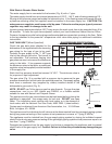
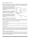
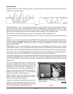
Check Rotation (Three-Phase Machines Only)
Three-phase motors must rotate in the direction of the arrow on the pump housing. In order to check
rotation, the motor fan cover must be removed. Close the machine doors and press the power switch
to ON. When the machine is completely filled, place the cycle switch (located on the side of the control
box) on MANUAL and place the WASH / RINSE switch (located under the cycle switch) on WASH. The
motor fan must rotate in the direction of the arrow on the pump housing.
If the rotation is incorrect, DISCONNECT ELECTRICAL POWER SUPPLY and interchange any two
of the incoming power supply leads. Reconnect the power supply and verify correct rotation. Replace
the motor fan cover.