


– 6 –
INSTALLATION
Immediately after unpacking the disposer, check for possible shipping damage. If the disposer is found
to be damaged, save the packaging material and contact the carrier within 15 days of delivery.
Prior to installation, test the electrical service to make sure that it agrees with the specications on
the disposer data plate.
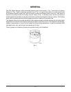
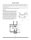
Temporary support, such as blocking, must be provided for the disposer during installation to avoid
excessive stress at welded or soldered cone to table connection.
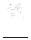
ASSEMBLY
To attach the disposer assembly to the cone for a regular
duty installation, see Fig. 2. Note the top clamp ring (1,
Fig. 2) has drilled holes and the bottom clamp ring (3,
Fig. 2) has threaded holes. Using ve screws (2, Fig. 2)
assemble rear halves of clamp rings to the back of the
disposer ange (4, Fig. 2). Lift the disposer into position
on the cone ange (5, Fig. 2) and assemble front halves
of clamp rings using remaining ve screws. Tighten all
screws nger tight. Rotate disposer to desired position
and tighten all screws evenly to form a water-tight joint.
To install accessory group E (sink adapter for 3-1/2" to
4" sink opening), use the short upper housing. See (2,
Fig. 4) and the accessory group parts catalog.
Fig. 2
Fig. 3
6 1/2"
8 3/8"
15" OR 18"
10 1/4"
WASTE EXI
T
7"
4 1/2" 6 1/2"
21-3/4" FD4/50,75 3 PH.
22-3/4" FD4/50,75 1 PH.
FD4/125 3 PH.
23-5/8" FD4/125 1 PH.
LONG UPPER HOUSING
WASTE OUTLET