


– 7 –
PLUMBING CONNECTIONS
Plumbing connections must comply with applicable sanitary, safety, and plumbing
codes.
Drain
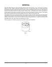
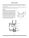
The disposer is furnished with a 1-1/2" O.D. waste discharge
spout suitable for connection to a standard trap. Install
waste lines with the shortest possible run and best fall. The
waste exit must not be higher than the center line of the
waste outlet (1, Fig. 3 and 1, Fig. 4). Old waste lines must
be thoroughly cleaned. Ream burrs from cut pipe ends and
use ttings which will permit unrestricted ow. Drum traps
and grease traps must NOT be used.
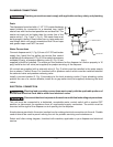
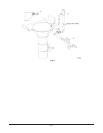
Water Connections
Connect disposer swirl (1, Fig. 5) from a 3/4" IPS cold water
supply line. Install the ve gallon per minute ow control
supplied with the disposer (2, Fig. 5). If the water line pressure
exceeds 60 psig, a pressure reducing valve (6, Fig. 5) (not
supplied) should be installed. The minimum ow pressure for the disposer to function properly is 16
psig. Install a shut-off valve (not supplied) for proper servicing of the disposer.
All controls are supplied with a solenoid valve (4, Fig. 5) which must be installed in the water supply
line as shown. Control Group 3 is furnished with a pressure switch which must be installed between
the solenoid valve and pressure reducing valve.
Install a vacuum breaker (3, Fig. 5) according to the local plumbing codes. If local plumbing codes
prohibit the use of a vacuum breaker, install an air gap water inlet (not supplied) observing the local
codes.
ELECTRICAL CONNECTION
Electrical and grounding connections must comply with the applicable portions of
the National Electrical Code and/or other local electrical codes.
Disconnect the electrical power to the machine and follow lockout/tagout procedures.
This unit must be connected to a dedicated, acceptable motor control switch with a marked OFF
position to disconnect the appliance from all ungrounded supply conductors. The switch must be
mounted within sight of the disposer or sink opening for the disposer.
Knockouts are provided in the motor junction box for making electrical connections to the unit. Flexible
conduit should be used to permit moving the unit for periodic servicing and maintenance.
Select and follow wiring diagram, furnished with machine, applicable to your disposer and electrical
service.
7"
WASTE EXI
T
9 1/8"
SHORT UPPER
HOUSING
1
2
WASTE OUTLET
Fig. 4