


– 4 –
LEGS OR CASTERS
WARNING: THE CABINET MUST BE BLOCKED AND STABLE
BEFORE INSTALLING LEGS OR CASTERS.
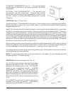
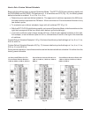
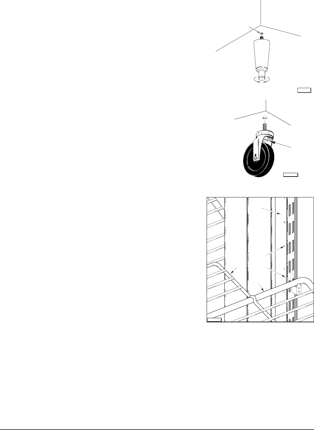
Legs (Fig. 5)
To install the legs, raise and block the reach-in a minimum of 7
"
from
the floor and thread the legs into the Threaded Holes on the bottom
of the cabinet. This unit must be level in order to operate properly.
Turn the adjustable feet in or out as required to level the unit
front-to-back and side-to-side.
NOTE: Three-section front opening cabinets come with five legs,
the fifth leg should be placed in the front center threaded hole. In the
case of a three section pass through cabinet, a sixth leg is included
for the rear center hole. Failure to install these legs in the proper
location may result in damage to the cabinet.
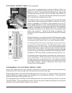
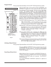
Casters (Fig. 6)
Use casters only on reach-in models with self-contained refrigeration
systems that have cord and plug electrical connections. Raise and
block the cabinet a minimum of 7" from the floor. Thread the casters
into the holes in the bottom of the cabinet (Fig. 2). Casters with
brake should be installed at the front. Securely tighten the caster
with the octagon shaped Bolt head underneath — not the round
flange on top.
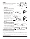
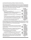
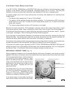
Shelves (Fig. 7)
If purchased, the shelves and shelf clips are shipped with the
cabinet. Insert the shelf clips into the pilaster and install the
shelves. Index holes are provided in the pilaster to help in
leveling the shelves.
Bonus shelves are provided to fill the space between the
shelves. These are positioned and supported by the shelves.
NOTE: Loosen all thumbscrews which secure shelf pilasters
and light cover(s) prior to placing product in cabinet.
Thumbscrews should be loose enough to remove with your
fingers so parts can be readily removed for cleaning without the
use of tools. Failure to comply with this request will invalidate
the NSF listing.
Utility Base (Optional)
If your unit comes with a utility base, we recommend securing the base to the floor to prevent damage
to the floor outlet due to accidental movement. The utility base is secured to the cabinet with four bolts,
one at each corner. The utility base is mounted at the factory. With the cabinet in its final installed and
leveled position, apply a bead of NSF approved sealant (not supplied) around the bottom. Access
covers, secured with screws, are provided on the left side and front for attaching the power supply cord
to a floor outlet underneath the cabinet.
Curb
The cabinet may be installed on a curb without legs or casters; the typical curb must be recessed a
minimum of 1
3
/8" from the front of the cabinet (and rear if it is a pass through) to allow room for the hinges.
PL-53353
BOLT
RAISE
THREADED HOLE
LOWER
PL-56125
Fig. 6
Fig. 5
PL-50910
BONUS
SHELF
SHELF
SHELF
CLIP
PILASTER
INDEX
HOLE
COLD AIR
DUCT
Fig. 7