D896 AUTOMATIC VENT DAMPER
68-0186
4
IMPORTANT
1. The atmospheric draft hood outlet area must be
smaller or equal to the inlet area of the damper
assembly.
2. If a second gas valve needs to be installed, refer
to the gas valve manufacturer instructions for the
procedure.
3. Using a dual automatic valve combination gas
control or two separate gas valves is required
with the D896.
4. Do not use with L8148 or L8124 with manual/
automatic switch because the switch can override
the safety interlock in the system wiring and
cause a hazardous condition.
5. Do not install on an appliance equipped with an
automatic valve with a manual opener unless the
manual opener is rendered inoperative or the
automatic valve is replaced with an automatic
valve without a manual opener.
6. On retrofit applications, installation identification
label (provided) must be filled out by installer and
applied to outside of cover.
INSTALLATION
When Installing this Product…
1. Read these instructions carefully. Failure to follow them
could cause a hazardous condition.
2. Check the ratings given in the instructions and on the
product to make sure the product is suitable for your
application.
3. Installer must be a trained experienced service
technician. The D896 must be installed in compliance
with local codes or the Natural Gas Installation Code
CAN/CGA-B149.1-B149.1-M91 and CSA C22.2 #3
Electrical Features of Fuel Burning Equipment, or the
National Fuel Gas Code (ANSI Z223.1—NFPA 54) and
the National Electrical Codes (ANSI C1—NFPA70). Use
the ANSI Standard Z21.66-1994 included at the end of
this specification during installation.
NOTE: In Canada, the damper is not certified for
retrofit application. Certification for the
suitability of the damper and appliance
combination must be determined by the
Canadian Gas Association.
4. Install only on an appliance connected to a factory built
chimney or vent that complies with a recognized
standard, or to a masonry or concrete chimney that is
lined with a material acceptable to local code.
5. After installation is complete, check out product
operation as provided in the Checkout section. See
Exhibits A and B at the end of this specification.
CAUTION
Can cause electrical shock or equipment damage.
1. Disconnect power supply.
2. Do
not
install within 6 in. (152 mm) of combustible
materials.
3. Do
not
negate the action of any existing safety or
operational control.
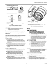
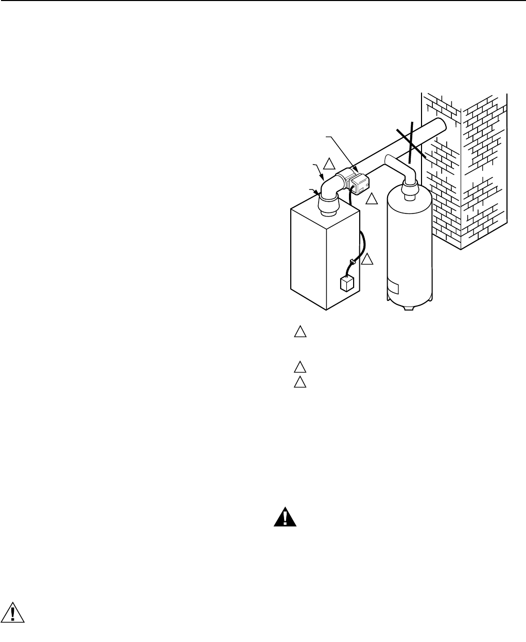
Location
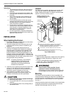
The D896 must be installed
after
the furnace or boiler draft
hood. See Fig. 2. Make sure the D896 Motor Actuator is
readily visible and accessible. The damper must be located
where air can freely circulate around it.
M11370
2
1
3
WARNING: DO NOT INSTALL THE
VENT DAMPER WITHIN 6 IN. (152 mm)
OF COMBUSTIBLE MATERIAL.
NO
CHIMNEY
WATER HEATER
FURNACE OR BOILER
INSTALL THE VENT DAMPER TO SERVICE ONLY THE SINGLE
APPLIANCE FOR WHICH IT IS INTENDED. IF IMPROPERLY
INSTALLED, A HAZARDOUS CONDITION, SUCH AS AN EXPLOSION
OR CARBON MONOXIDE POISONING, COULD RESULT.
DO NOT INSTALL THE VENT DAMPER ON VENT PIPE CURVE.
DO NOT RUN WIRES NEAR HIGH TEMPERATURE SURFACES.
USE STAND-OFF BRACKETS IF NECESSARY.
2
1
3
VENT PIPE
CURVE
DRAFT
HOOD
D896 MOTOR
ACTUATOR
Fig. 2. D896 location.
Do
not
install the D896:
— Where the stack temperature is higher than 575°F (284°C).
— Where the ambient temperature is higher than 150°F
(66°C).
— In small or enclosed spaces where temperature can
exceed 150° F (66°C). See WARNING following.
— On the vent pipe curve. See Fig. 2.
WARNING
Severe illness or death possible. Prevent
explosion or carbon monoxide poisoning.
Overheating can cause premature device failure. Be
sure the D896 is used to control only one appliance.
Mounting
The damper must be mounted as close as possible to the
draft hood without modifying the draft hood. The D896 can be
mounted vertically or horizontally. When vertically mounting
the vent damper, the motor actuator can be in any position.
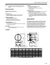
See Fig. 3.
Horizontal mounting requires the actuator to be located within
45 degrees directly above or directly below the horizontal
diameter of the stack pipe. See Fig. 2 and 3.


