D896 AUTOMATIC VENT DAMPER
68-0186
9
Thermostat Setting Symptom Possible Cause Action
Set thermostat 10°F
above room temperature
to call for heat.
No response from D896. Incorrect wiring or blown
fuse.
• Check the circuit breaker or fuse and,
if necessary, reset or replace.
• Check the transformer and limit
control.
• Check for 24 Vac across resistor R1.
• Check for 24 Vac at the S8600, S8610
and L8148E.
• Check wiring and cable connections.
24 Vac is present, damper
is open, CALL FOR HEAT
LED is on, IGNITION GAS
PWR LED is on, but no
heat is produced.
Appliance ignition
system malfunction.
Check appliance ignition system.
24 Vac is present, damper
is open, CALL FOR HEAT
LED is on, IGNITION GAS
PWR LED is off, no heat is
produced.
D896 malfunction. Replace the D896.
24 Vac is present, damper
is closed, CALL FOR HEAT
LED is off and no heat is
produced.
Incorrect wiring or D896
malfunction.
Check all wiring and cable connections.
• If 24 Vac is present across resistor
R1, replace the D896.
• If 24 Vac is not present across R1,
check the appliance ignition
system.
24 Vac is present, damper
is closed and CALL FOR
HEAT LED is off.
Incorrect wiring or D896
malfunction.
Check all wiring and cable connections.
• If 24 Vac is present across resistor
R1, replace the D896.
• If 24 Vac is not present across R1,
check the appliance ignition
system.
24 Vac is present, damper
is closed and CALL FOR
HEAT LED is on.
Incorrect wiring or D896
malfunction.
If wiring is correct and the damper does
not fully open after approximately 30
seconds, replace the D896.
Set thermostat 10°F
below the room
temperature to end the
call for heat.
LEDs turn off, but damper
does not close in
approximately 30 seconds.
Incorrect service switch
setting or D896
malfunction.
• Check if the service switch is in the
normal (NORM ) position. If not, move
the switch to the NORM position.
• If service switch is in the NORM
position, replace the D896.
NOTE: If there is a power failure, the damper remains
exactly where it is at the moment of failure (open,
closed or any position in between). When power is
restored, the damper opens if the thermostat is
calling for heat or closes if the thermostat is not
calling for heat.
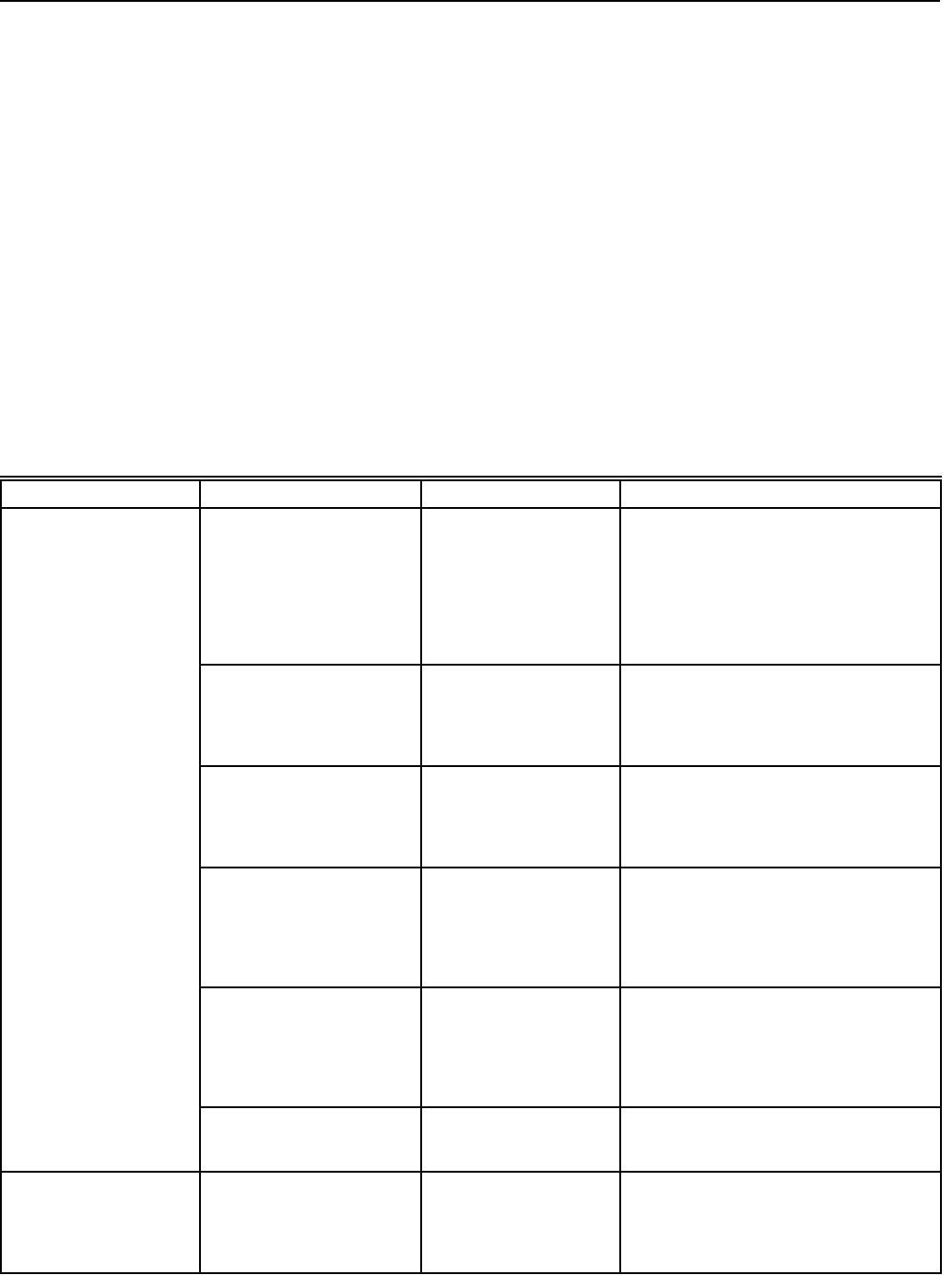
If system fails to start, set the thermostat 10°F (6°C) below
the room temperature for approximately three minutes, and
refer to Table 2 to troubleshoot the system.
INSTRUCTIONS TO THE HOMEOWNER
A yearly inspection by a trained, experienced service
technician is necessary for safe, efficient operation of the vent
damper and all flue product-carrying areas of the appliance.
The homeowner should check for deterioration from corrosion
and other sources between service technician calls. If
corrosion or other deterioration is noticed, contact your
heating contractor for repairs. The name of the original
installer of your vent damper is on the installation label.
Check vent damper operation as follows:
1. Turn the thermostat or controller below the room
temperature to turn off the furnace or boiler. Assure the
vent damper position indicator points to the closed
position. Refer to Fig. 11.
2. Turn the thermostat or controller above the room
temperature to call for heat. Assure the vent damper
position indicator points to the open position. Refer to
Fig. 11.
3. Turn the thermostat or controller below the room
temperature again. Assure the vent damper position
indicator returns to the closed position.
4. If the system has central air conditioning, set the
thermostat or controller to COOL and turn it below the
room temperature to call for cooling. Assure the cooling
system operates with the vent damper in the closed
position.
5. Return the thermostat or controller to the desired
settings.
Table 2. Troubleshooting.


