


D896 AUTOMATIC VENT DAMPER
68-0186
5
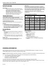
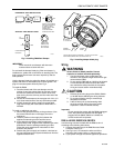
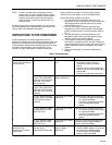
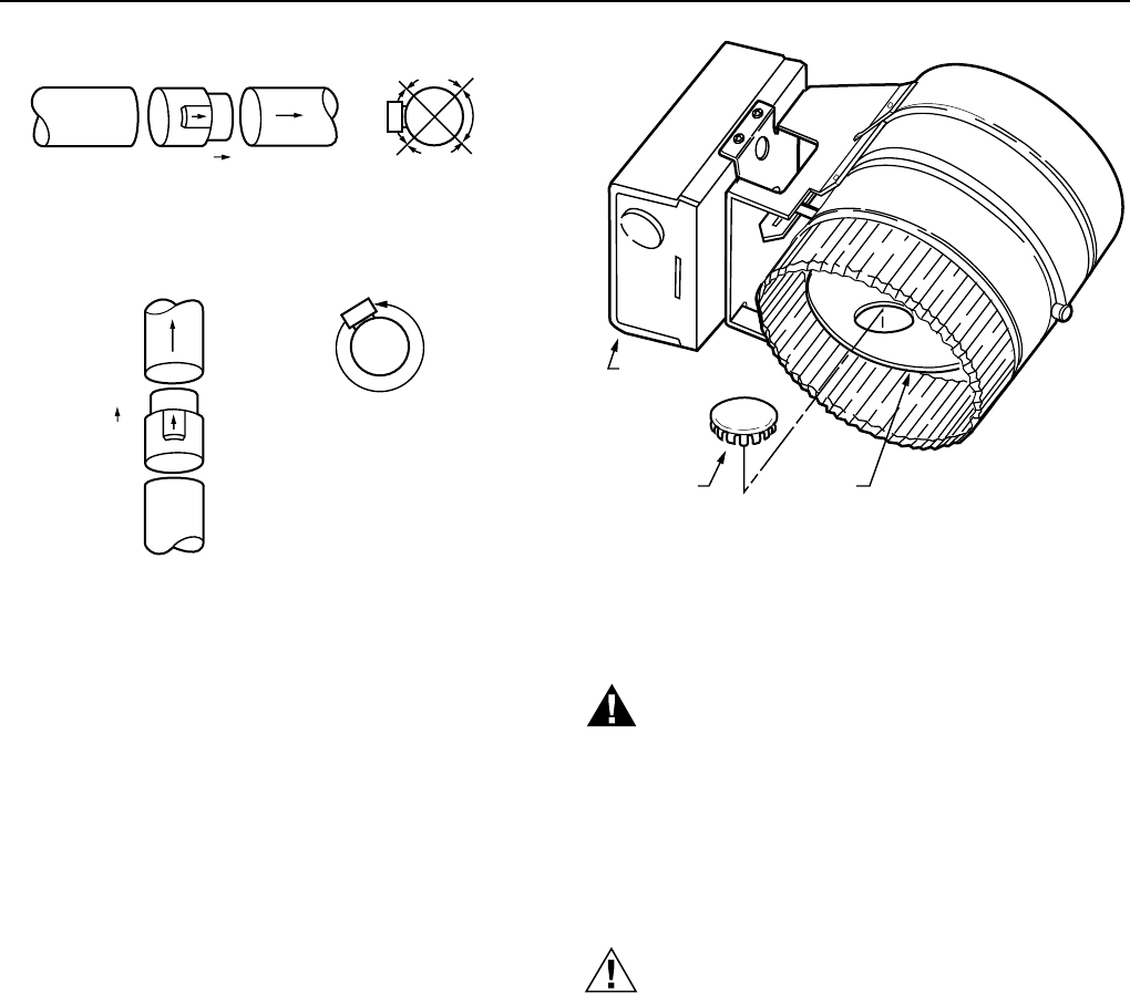
Fig. 3. Installing D896 Vent Damper.
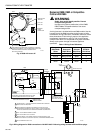
IMPORTANT
Never mount the vent damper with the motor
actuator above or below the vent.
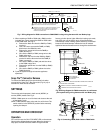
Do
not
install the damper blade plug if the vent damper is
installed on a system with a continuous or standing pilot. The
hole provides the minimum vent area required by code for
safe operation.
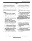
Use the damper blade plug when the damper is installed on a
system with either an intermittent pilot or direct ignition. The
plug will increase system efficiency. See Fig. 4.
To install the D896:
1. Push the female end of the vent damper over the
section of vent pipe coming from the furnace or boiler,
but after the draft hood. Push the section of the vent
pipe coming from the chimney over the male end of the
vent damper.
2. Secure the vent damper to the vent pipe with 1/2 in. (12
mm) sheet metal screws. Use only the holes provided.
3. Visually inspect the venting system for proper pitch.
Pitch must comply with local codes or ANSI Z223.1—
NFPA54.
To install an additional gas valve:
1. Shut off the gas and electricity to the gas burner. (Use
the manual shutoff valve in the supply line to the
appliance.)
2. Locate a position in the supply line between the
appliance automatic gas valve and the burner.
3. At the determined position, install an approved
appropriately-sized, single-function automatic gas valve
downstream from the existing automatic gas valve.
Follow the valve manufacturer instructions for flow
direction and position.
4. Restore the gas line supply and conduct a leak test on
the gas piping and control system downstream from the
appliance shutoff valve.
M11371
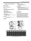
HORIZONTAL VENT INSTALLATION
FROM FURNACE
OR BOILER
FLOW
TO CHIMNEY
NO
NO
YES
YES
VERTICAL VENT INSTALLATION
TO
CHIMNEY
FLOW
FROM FURNACE
OR BOILER
INSTALL VENT
DAMPER WITH
ACTUATOR IN
ANY POSITION.
INSTALL VENT DAMPER
ONLY WITH ACTUATOR
TO SIDES OF VENT.
DO NOT MOUNT VENT
DAMPER WITH
ACTUATOR ABOVE
OR BELOW THE VENT.
D896
D896
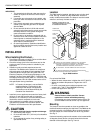
Fig. 4. Installing damper blade plug.
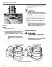
Wiring
WARNING
Severe illness or death possible. Prevent
explosion or carbon monoxide poisoning.
1. Use dual automatic valve combination gas
controls or two separate single function main gas
valves with the D896.
2. Do not use the D896 with an L8148 or L8124 with
a manual/automatic switch because the switch
can override the safety interlocks in the system
wiring and cause carbon monoxide buildup.
CAUTION
1. Remove the shorting plug on the S8600, S8610
or L8148E before attaching the wiring harness.
2. Do
not
permit device wiring to contact high
temperature surfaces.
3. Label all wires prior to disconnecting when
servicing controls. Wiring errors can cause
explosion or carbon monoxide buildup.
Important
Do not operate the system with the D896 unplugged.
Once the system has operated with the D896
plugged into the S8600, S8610 or L8148E, the
control module will not operate.
D896 to L8148E, S8600F,H,M; S8610F,H
Use the wiring harness included with the D896 to wire it
according to the following instructions:
1. Connect the molex plug to the D896 Harness Cable
Connector. See Fig. 5.
2. Use Fig. 6 and 7 to connect the other end of the
harness to the furnace, boiler or control module.
3. Cycle system through at least two appliance operations.
DAMPER
BLADE PLUG
DAMPER
BLADE
MOTOR
ACTUATOR
FOR DSI AND IP INSTALLATIONS ONLY – PLACE PLUG ON HOLE:
HOLD DAMPER BLADE AND PUSH DOWN ON PLUG.
M9675