


7
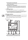
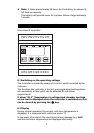
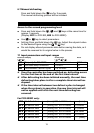
Terminal: Description:
1 - 2 T1 = Cold store sensor
3 - 4 T2 = Evaporator sensor
10 - 12 Mains = Power supply
13 - 15 V = Compressor contactor (cooling)
17 - 18 Ev = Evaporator fan (contactor)
20 - 21 Alarm = Remote alarm indicator; indicator lamp or
contactor (with RC-element)
23 - 24 Def = Defrost heating
(contactor) or hot gas valve
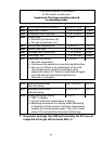
☛ The unit is equipped with an opto-decoupled electronic
alarm output.
Take note of the alarm output limit values.
¼ Supply voltage: Max. 250 V AC.
¼ Minimum load: 40 mA
¼ Maximum load: 80 mA
¼ If an inductive load (contactor or horn) is connected, connect
an RC element directly at its coil.
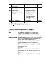
☛ Instructions:
¼ Pay attention to the contact loading of the relay
(8A / 5A resistive load, 2A / 1A inductive load). As a general rule,
contactors are recommended.
¼ The maximum tested sensor cable length is 50 m, with a minimum
cross section of 2 x 0.75 mm
2
. Solder the extension cable to the
sensor cable to prevent contact resistances.
¼ It is advisable to use shielded sensor extension cables.
All shields must be routed at the side of the controller to one
earth/protective potential. The extension cable shield must not be
connected on the sensor side, otherwise bonding currents may
occur via the shielding.
¼ The controllers are designed respecting the highest degree of
immunity to interference. If the local interference level exceeds the
immunity data might get lost (AL1 in display) and the controller
switches to the preprogrammed setting values. This is not a
mulfunction of the controller. In such cases the means to suppress
interference have to be improved (RC-elements, shielded lines).