


-- 5 --
462 06 1211 00
3/17/06
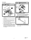
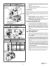
Typical Gas Valve Honeywell
SV9501
INLET
OUTLET
Pilot
Adjustment
Pilot
Outlet
Wiring Terminals
Outlet Pressure Tap
Connect manometer here to
check outlet pressure. Must be
adjusted per Table 1.
Inlet Pressure
Tap (Hidden)
25--22--25
Figure 8
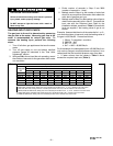
Typical Gas Valve Honeywell
VR8205S
Figure 9
V
T
25-- 24--98a
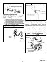
HONEYWELL
ON
OFF
Regulator Adjustment
Under Cap
Inlet
Pressure
Tap
1
/
8
NPT
INLET
OUTLET
Outlet
Pressure
Tap
1
/
8
NPT
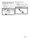
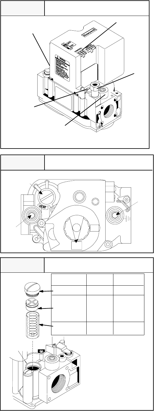
Typical Honeywell
Regulator Assembly
PRESSURE
REGULATOR
HOUSING
Cap Screw Black Silver
Pressure White White
Regulator
Adjusting
Screw
Stainless
Spring Red Steel
LP
Gas
Natural
Gas
Figure 10
4. Install the pressure regulator adjusting screw. This will set
the manifold pressure close to required setting for normal
operation.
5. Replace the regulator cap screw.
6. Attach gas valve conversion label (found in Honeywell con-
version kit) to gas valve.
Reassembly
Reassemble all parts in reverse order as removed. Attach Natural
Gas Conversion Label next to the unit rating plate. Fill out and
attach the Field conversion Label to the front exterior of the
furnace.
D Manifold Assembly -- Be sure to engage the main burner
orifices in the proper openings in the burners.
D Testing for leaks -- After reassembly, turn the gas on and
check all joints for gas leaks using a soapy solution. All
leaks must be repaired immediately.
Start--up and Check--out
1. Remove the plug from the Inlet Pressure Tap on gas valve
and install a manometer. (See Figures 7, 8, 9, & 10)
2. Open manual gas line valve to unit. Check for gas leaks and
correct as necessary. Check supply pressure. Refer to
Table 2 for proper supply pressure values. If not within
these limitations DO NOT OPERATE UNIT, contact gas
supplier.
3. Close manual gas line valve to unit, remove manometer and
replace inlet pressure tap plug.
Gas Valve Adjustment
4. With the gas valve knob in the OFF position, remove the
pressure tap plug from the outlet end of the valve, and con-
nect a “U” tube manometer to the pressure port. (See Fig-
ure7,8,9&10).
5. Turn the gas valve knob to the ON position and restore elec-
trical power to unit. Cycle the main burner on and off several
times to stabilize the pressure regulator diaphragm. This
MUST be done before an accurate pressure reading can be
obtained.
6. With the main burner on, readthe pressure gauge. Manifold
pressure should be adjusted to values from Table 2. Turn
pressure regulator adjusting screw clockwise to increase or
counterclockwise to decrease manifold pressure. Burner
Input must not exceed nameplate rating. Refer to Section
“Checking Input Rate”.
7. Turn gas valve to OFF. Remove the pressure gauge and re-
place the pressure tap plug and pressure regulator cap
screw.
8. With gas valve on, observe furnace through two or more
complete cycles to be sure all controls are operating.