


18
3)Screwthe6threadedwoodinsertsintothe1/4"holesdrilledinthepreviousstep.Make
sure that the inserts are threaded straight and that the tops of the inserts are ush to
the overlay panel surface. Otherwise, the overlay panel cannot be properly fastened to
the door.
4) Mount the door handle hardware. Hoshizaki recommends that the door handle
hardware be mounted on the edge opposite of the door hinge side (optional hinge
reversal is covered in step 6). Countersunk screw heads are required to ensure that the
hardware fasteners do not interfere with the overlay panel tting ush with the door.
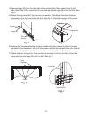
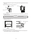
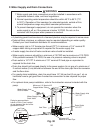
5) While maintaining a hold on the door, remove the hinge stop pin from hinge (B). Pull out
the bottom of the door slightly and gently remove the door from hinge (A). See Fig. 10.
If you are leaving the door right-hinged, skip to step 7. If you would like to reverse the
door hinges, proceed to step 6.
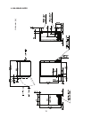
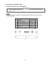
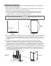
(3) Fabrication of Overlay Panel
Fabricate the overlay panel as outlined in the applicable specication on the previous
pages and the instructions below.
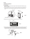
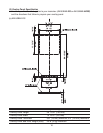
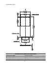
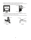
1)Routachannelatthebottomoftheoverlaypaneltotheproperdimensions.See"(C)
RoutedArea"inthespecicationdiagramandFig.8.
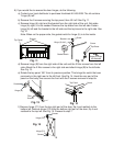
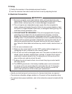
2)Drillsix1/4"diameter(hardwoodmayrequireslightlylargerdiameter)holes3/8"
(10mm)deepinthelocationsdesignated.See"(A)ThreadedInserts"and"(B)
ThreadedInserts"inthespecicationdiagramandFig.9.
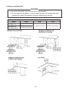
CAUTION
Use care when drilling holes for mounting hardware. All drilled holes must be
straight and drilled to the correct diameter and depth.
Routed Channel
Holes
Holes
Fig. 8
Fig. 9
Fig. 10
Hinge Stop Pin
Hinge (B)
Hinge (A)