


7
2. Features
The control board provides the following safeguards:
• Provides component protection during low water supply.
• Purges remaining ice in the evaporator at startup and shutdown.
• Provides short cycle protection for the compressor.
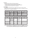
a) LED Lights
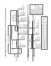
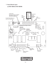
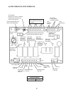
The "POWER" LED indicates control voltage and will remain on unless a control
voltage problem occurs. An LED illuminates for each relay as it is energized. For more
information, see "II.C. Sequence of Operation."
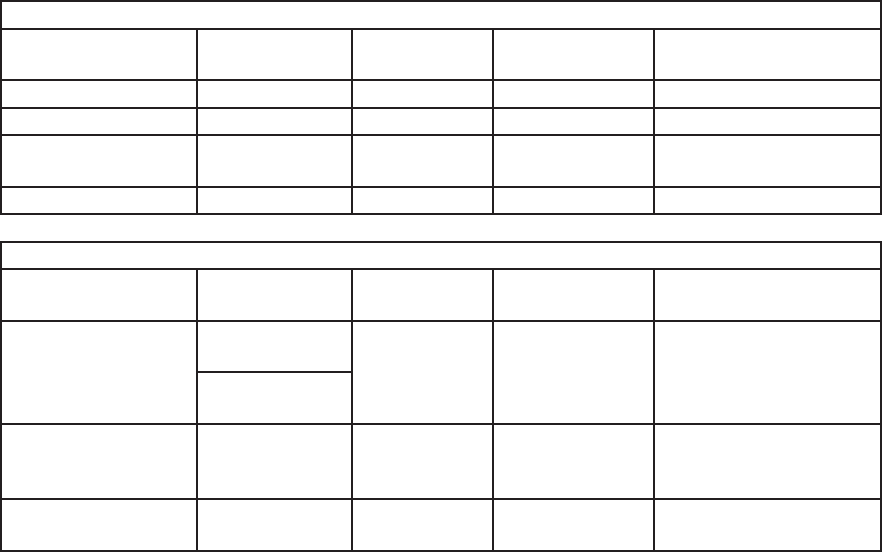
Icemaking
Cycle (Relay) LED
Energized
Components
Time LEDs are
On
Frequency LEDs are
On
Fill POWER only WV N/A As Needed
Ice Purge (X)
GM GM, HTR 60 seconds N/A
Freeze (X, X)
GM, COMP
GM, HTR,
Comp, FMS
N/A N/A
Drain Valve (X6) FLUSH DV 0 Minutes Every Hours
Dispensing
Relay LED
Energized
Component
Time LEDs are
On
Frequency LEDs are
On
Ice Dispense (X4)
Push Button
DM
IDM
60 seconds
maximum
N/A
Opti Serv
ICE
Agitating Motors (X3) AM AM .6 seconds
Every seconds of
accumulative dispense
time
Water Dispense (X5)
(Opti Serv Only)
WTR WTR N/A N/A
Legend: AM–agitating motors, Comp–compressor; DV–drain valve; FMS–self-contained
fan motor; GM–gear motor; HTR–extruding head heater; IDM–ice dispensing
motor, shutter solenoid; WTR–dispensing water valve; WV–inlet water valve