


ENGLISH
2
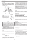
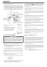
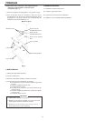
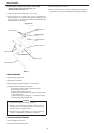
5) Seal the seam between the icemaker and the Storage Bin with food
grade sealant.
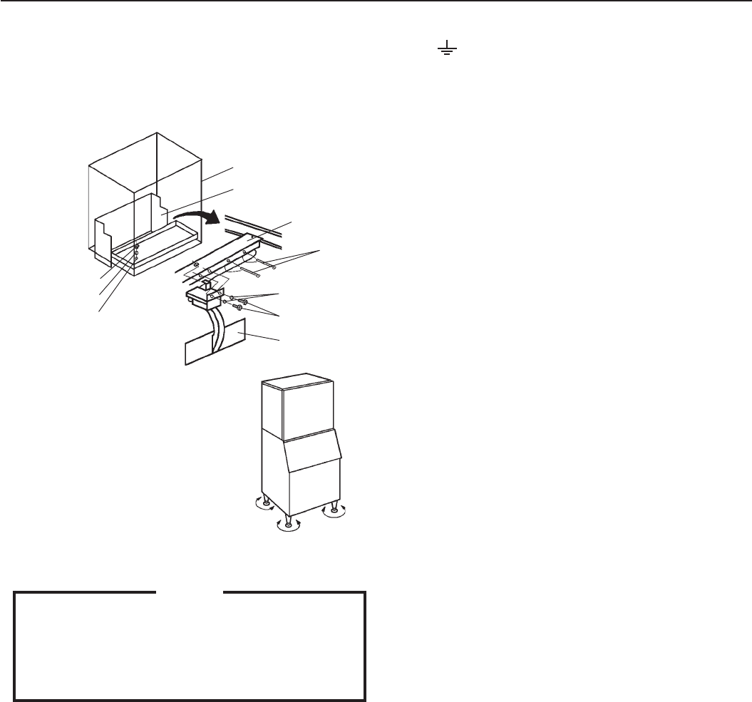
6) Remove the Drain Pipe Collar and Drain Pan. Secure the Bin Control
Switch to the Mounting Frame using the two bolts and flat washers
provided. Fix the Bin Control Switch wiring with the two nylon ties.
Place the Ice Chute on the Unit Frame, and refit the Drain Pan in its
correct position. See Fig. 5.
Fig. 5
Bin Control Switch
Bolt
Drain Pipe Collar
Packing
Drain Pan
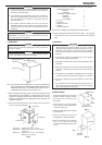
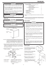
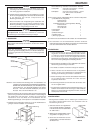
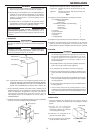
7) Refit the panels in their correct
positions.
8) Adjust the four legs on the bottom
(adjustable from 0 to 25.4 mm) to have
the icemaker perfectly horizontal. Use
the spirit level. See Fig. 6.
Washer
Tie
Mounting Frame
Unit Frame
Ice Chute
Adjust legs
Fig. 6
4. ELECTRICAL CONNECTIONS
WARNING
THIS APPLIANCE MUST BE EARTHED
This icemaker requires an earth that meets the national and local
electrical code requirements. To prevent possible severe electrical
shock to individuals or extensive damage to equipment, install a
proper earth wire to the icemaker. Remove the plug from the
mains socket before any maintenance, repairs or cleaning is
undertaken.
* This icemaker should not be installed:
a) Where the power supply is not within the range of 220 - 240V.
b) Where the icemaker cannot be plugged directly into its own power
supply without using an extension cord or sharing a receptacle.
* The main control box fuse is rated at 5A and should only be replaced
by a qualified service engineer.
* Usually an electrical permit and services of a licensed electrician are
required.
* If the supply cord and the plug should need to be replaced, it should
only be done by a qualified service engineer.
For the U.K. and the Republic of Ireland only
* The wires in the mains lead are coloured in accordance with the
following code:
Green & Yellow = Earth
Blue = Neutral
Brown = Live
As the colours of the wire in the mains lead of this appliance may not
correspond with the coloured markings identifying the terminals in
your plug, proceed as follows:
The wire which is coloured Green-and-Yellow must be connected
to the terminal in the plug which is marked with the letter E or by the
symbol or coloured Green or Green-and-Yellow. The wire which
is coloured Blue must be connected to the terminal which is marked
with the letter N or coloured Black. The wire which is coloured
Brown must be connected to the terminal which is marked with the
letter L or coloured Red.
* Should the socket outlets in the installation site not be suitable for the
plug supplied with your product, the plug must be removed (cut off if
it is moulded on plug) and an appropriate plug fitted.
If the non-rewirable plug has been cut from the power supply cord,
it must be disposed of. There should be no attempt to reuse it.
Inserting such a plug into a socket elsewhere presents a serious
risk of electrical shock.
* The non-rewirable plug must never be used without a fuse cover
being fitted.
The correct replacement for the detachable fuse cover is identifiable
from the manufacturer’s reference number stamped on the plug.
Supply of replacement fuse covers can be obtained from Hoshizaki
Parts/Service Centres.
Fuses should be rated at 13A and approved to BS 1362.
5. WATER SUPPLY AND DRAIN CONNECTIONS
(For the U.K. only, the connections must be in accordance with current
requirements of the Model Water Byelaws 1986 SI No. 1147)
* Only potable water should be used for the icemaker.
* Water supply pressure should be minimum 0.5 bar and maximum 8
bar. If the pressure exceeds 8 bar, use a proper pressure reducing
valve. Do NOT throttle back the supply tap.
* A plumbing permit and services of a licensed plumber may be required
in some areas.
* The icemaker drain is gravity flow, so ensure drain pipe has an
adequate pitch or fall.
* Water should drain into an open trap.
* The Storage Bin has two drain outlets. The upper/outer one is for
dump from the icemaker, and the lower/inner is for the Bin. The two
drain lines must be separated to prevent a backflow into the Storage
Bin.
* On water-cooled model, a back flow preventer may be required in
the cooling water circuit.
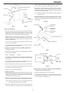
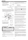
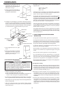
[Air-Cooled Model]
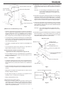
1) Attach the angled end of white flexible inlet hose (accessory) to the
G3/4 fitting on the left side of the icemaker as indicated, ensuring
rubber sealing washer is correctly positioned. Hand tighten
sufficiently to provide leak free joint (Fig. 7).
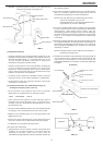
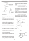
2) Attach the other end of inlet hose to the water tap (Fig. 8), noting
washer is correctly positioned before hand tightening as above. It
is a wise precaution to have a stop valve within easy reach.
3) Hand tighten grey flexible outlet hose (accessory) onto the R3/4
fitting on the left side of the Storage Bin as indicated, ensuring
rubber washer is correctly positioned to obtain a leak free joint. The
pipe can be cut to length as necessary to suit position of main drain.
Note: Jointing compounds should be approved and suitable for
potable water use.