


ENGLISH
3
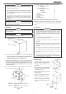
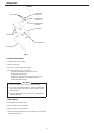
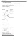
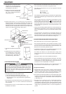
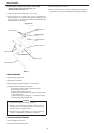
Fig. 7 Fig. 8
[Water-Cooled Model]
* Hoshizaki recommends that the water-cooled Condenser should be
connected to a closed circuit recirculating type cooling system
utilizing a tower, water chiller or similar (see Fig. 15 and 16). Water
make up should be via a ball valve/break tank arrangement.
* Whilst connecting a water-cooled Condenser to a mains water
(potable) supply will not affect the performance of the machine, it
will most certainly cause a high use/waste of a valuable resource
and is not recommended.
* The services of a licensed or coded plumber should be used to
ensure a correct installation.
* The connections should be made properly in compliance with the
applicable national or local regulations.
[a] Standard connections according to WRC regulations in
U.K. (Fig. 9 and 10)
* When selecting a Cooling Tower, refer to the following peak values of
heat flow in the Condenser:
Model IM-240AWME: 5235 W
* Pipes between the Cooling Tower and the icemaker should be at least
20 mm DIA to reduce pressure loss, even though the icemaker fittings
are 13 mm DIA.
* Pressure loss in the water circuit inside the unit will be 5 to 6 m when
the cooling water flows at the ratio of 4 to 5 lit/min.
* Select a Circulating Pump referring to the above values of heat flow.
* Do not use a Cascade Pump, or the Water Regulator will vary the
flow and stop it during the defrost cycle.
* The Strainer must be cleaned periodically.
[Icemaker Connections]
1) Attach the angled end of white flexible inlet hose (accessory) to the
G3/4 fitting on the left side of the icemaker as indicated, ensuring
rubber sealing washer is correctly positioned. Hand tighten
sufficiently to provide leak free joint.
2) Attach the other end of inlet hose to the water tap (Fig. 8), noting
washer is correctly positioned before hand tightening as above.
Note: If filtration or treatment is used, ensure icemaker section only
is on treated water supply, not the Condenser.
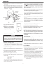
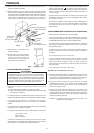
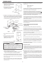
3) Attach grey flexible outlet hose (accessory) to the R3/4 fitting on the
rear of the icemaker as indicated (Fig. 9), confirming fitment of
Water
Supply Tap
Inlet Hose
Water Supply Inlet G3/4
Drain Outlet R3/4
Inlet Hose
Outlet Hose
rubber washer before finally hand tightening the joint. This pipe can
be cut to length as necessary to suit position of main drain.
4) By means of a suitable spanner or wrench, tighten the 1/2-3/4
nipples (accessory) into the Rc1/2 fittings on the rear of the icemaker
as indicated. P.T.F.E. tape and/or a suitable sealing compound should
be used to obtain a leak free joint.
Note: Jointing compounds should be approved and suitable for
potable water use.
5) Connect the Condenser cooling circuit to the free end of 1/2-3/4
nipples as indicated (Fig. 9) using a suitable rigid type pipe. P.T.F.E.
tape and/or a suitable sealing compound should be used to obtain a
leak free joint.
[b] Connections according to regulations other than WRC by
utilising accessory hoses (Fig. 11)
1) Follow the instructions from 1) to 4) in [a] above.
2) For Condenser connections, use supplied accessory hoses and
make the same connections as 1) to 3) in [a] above to the free end
of 1/2-3/4 nipples as indicated (Fig. 11).
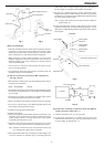
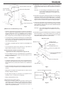
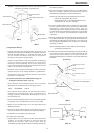
Fig. 9
Potable Water
Inlet G3/4
Inlet Hose
Drain Outlet R3/4
Outlet Hose
Cooling Water
Inlet Rc1/2
Cooling Water
Outlet Rc1/2
1/2-3/4 Nipple
Condenser Cooling Circuit
Icemaker
Bin
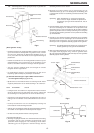
Fig. 10
Icemaker Cooling
Tower
Flow Control Valve
Strainer Pump
P