


10
6)
Check the water supply and drain connections for
water leaks.
7) Turn off the power supply, and remove the Front
Panel.
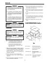
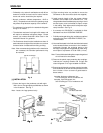
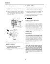
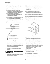
8)
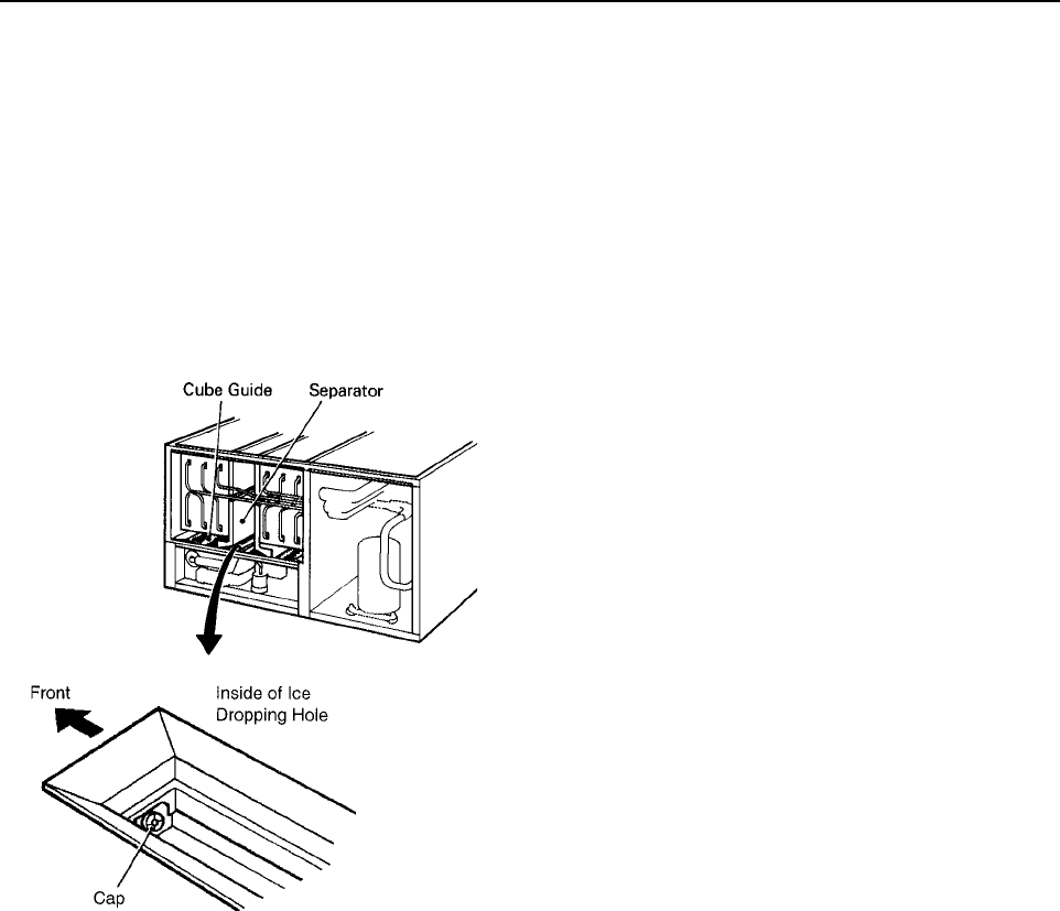
Remove the Insulation Panel. Remove the Cap
located on the front bottom part of the Ice Dropping
Hole. Drain the Water Tank to flush any loose
debris. See Fig. 12.
Fig. 12Fig. 12
Fig. 12Fig. 12
Fig. 12
9)
Replace the Cap, Insulation Panel and Front Panel
in their correct positions.
10)
Clean the Storage Bin.
11) Turn on the power supply, and start the
automatic icemaking process.
12) Wait until a complete icemaking and defrost cycle
is completed.
BIN CONTROL CHECKBIN CONTROL CHECK
BIN CONTROL CHECKBIN CONTROL CHECK
BIN CONTROL CHECK
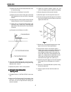
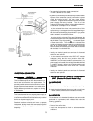
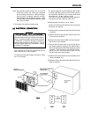
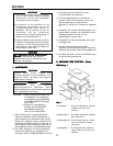
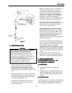
1) With the Front Panel in place, remove the thumb-
screws along the upper edge of the storage bin ice
deflector and allow it to pivot on the side fixings.
2) Hold some ice against the Bin Control Bulb. The
icemaker should stop within 6 to 10 seconds.
3) Replace the thumbscrews and close the bin door.
4) Check that the icemaker re-starts.
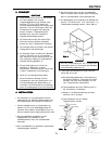
10. OPERATION10. OPERATION
10. OPERATION10. OPERATION
10. OPERATION
The steps in the sequence are as follows:
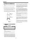
1) 1 Minute Fill Cycle
The unit always starts in the 1 minute fill cycle. When
power is applied to the unit, the water valve is ener-
gized and the fill period begins. After 1 minute the
board checks for a closed float switch. If the float
switch is closed the harvest cycle begins. If not,
the unit will not start without adequate water in
the sump. This serves a low water safety shut off. The
water valve will remain energized through additional
1 minute cycles until water enters the sump and the
float switch closes.
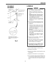
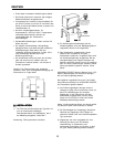
2) 1st Harvest Cycle
The compressor starts, hot gas valve opens, water
valve remains open and harvest begins. As the
evaporator warms, the thermistor located on the
suction line checks for a 9°C temperature. When 9°C
is reached, the harvest is turned over to the adjust-
able control board defrost timer which is factory set
for normal conditions. This adjustment can vary the
defrost timer from 1 to 3 minutes.
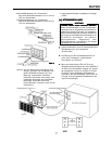
3) Freeze Cycle
After the timer terminates the harvest cycle, the hot
gas and water valves close, and the ice production
cycle starts. For the first 5 minutes the controller
board will not accept a signal from the float switch.
This 5 minute minimum freeze acts as a short cycle
protection. At the end of 5 minutes the float switch
assumes control. As ice builds on the evaporator the
water level in the sump lowers. The freeze continues
until the float switch opens and terminates ice pro-
duction.
ENGLISH