


19
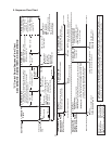
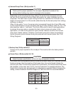
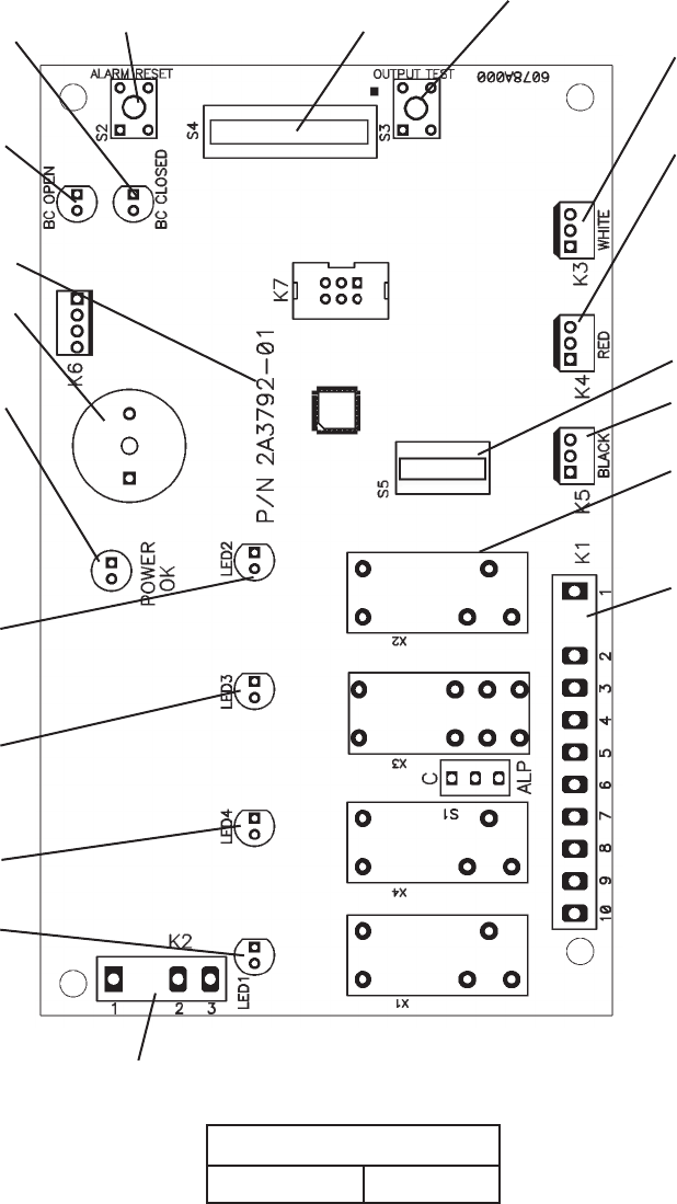
1. Control Board Layout
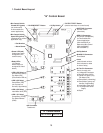
"G" Control Board
Part Number 2A3792-01
"G" Control Board
• "ALARM RESET" Button
• "OUTPUT TEST" Button
(used to test relays on control board)
• WHITE K3 Connector
Harvest Control
(thermistor)
• RED K4 Connector
K4 Jumper (4A4883G01)
for Thermostatic Bin
Control Application
(KM-1301SAH-E) or
Mechanical Bin Control
(KM-1301SWH-E,
KM-1301SRH-E)
• Label
(control board revision
level indicated on label
on side of relay)
• BLACK K5 Connector
Float Switch
• Part Number
• K1 Ten-Pin Connector
Pins #1 through #10
#1, 9 Magnetic Contactor
#2 Hot Gas Valve (HGV)
#3 Liquid Line Valve (LLV),
Fan Motor (FM)
#4 Pump Motor (icemaking)
#5 Pump Motor (pump-out,
harvest (if applicable))
#6 Inlet Water Valve (WV)
#7, 10 Component Power
Supply
#8 Open
• Bin Control Switch
Open LED (yellow)
(mechanical bin control
application only)
• S4 Dip Switch
• Bin Control Switch
Closed LED (green)
(on continuously
in thermostatic bin
control application)
• Alarm Buzzer
• Power LED (red)
(lights when power
is supplied to the
control board)
• LED 2 (X2 Relay)
Hot Gas Valve (HGV)
Fan Motor (FM)
(FM off when LED on)
• LED 3 (X3 Relay)
Pump Motor (PM)
(on at pump-out,
harvest (if applicable))
• LED 4 (X4 Relay)
Inlet Water Valve (WV)
• LED 1 (X1 Relay)
Compressor (Comp),
Fan Motor-Remote
(FMR)
• K2 Connector
Transformer
• S5 Dip Switch
• Relay LEDs
(4) (indicate
which relays are
energized as listed
below)