


13
B. Sequence of Operation
1. Sequence Cycles and Shutdown
The steps in the sequence are as outlined below. When power is supplied, a 5-second
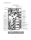
delay occurs at startup. Note that the order of the LEDs from the outer edge of the control
board is 1, 4, 3, 2.
a) One Minute Fill Cycle
LED 4 is on. WV opens and the ll period begins. After 1 minute, the control board
checks for a closed F/S. If F/S is closed, the harvest cycle begins. If not, WV will remain
energized through additional 1 minute cycles until water enters the sump and F/S closes.
This serves as a low water safety to protect the water pump.
b) Initial Harvest Cycle
LEDs 1, 4, and 2 are on. WV remains open, Comp and FMR energize, HGV opens,
and harvest begins. As the evaporator warms, the thermistor located on the suction
line checks for a 48°F (9°C) temperature. When 48°F (9°C) is reached, a 3.9 kΩ signal
turns the harvest over to the adjustable harvest timer which is factory set for normal
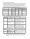
conditions. The timer has settings of 60, 90, 120, and 180 seconds (dip switch 1 & 2). The
water valve is open during harvest for a maximum of 6 minutes or the length of harvest,
whichever is shorter. When the harvest timer completes its count down, the harvest cycle
is complete and the freeze cycle starts. The minimum total time allowed by the control
board for a complete harvest cycle is 2 minutes.
c) Freeze Cycle
LED 1 is on. Comp and FMR continue to run, PM and FMS energize, LLV opens, HGV
and WV close and the freeze cycle starts. For the rst 5 minutes the control board will not
accept a signal from F/S. This 5 minute minimum freeze acts as a short cycle protection.
At the end of 5 minutes, F/S assumes control. As ice builds on the evaporator the water
level in the sump lowers. The freeze continues until F/S opens and terminates ice
production.
d) Pump-Out Cycle
LEDs 1, 3, and 2 are on. Comp and FMR continue to run, HGV opens, LLV closes, and
FMS deenergizes. PM stops for 2 seconds and reverses, taking water from the bottom of
the sump and forcing pressure against the check valve seat allowing water to go through
the check valve and down the drain. At the same time water ows through the small
tube to power ush the F/S. When the pump-out timer stops counting, the pump out is
complete.
Pump out always occurs on the 2nd harvest after startup. Then, depending on the control
board setting, pump out occurs every cycle, or every 2nd, 5th or 10th cycle (dip switch
5 & 6).