


3
CONTENTS
Important Safety Information ................................................................................................. 6
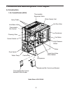
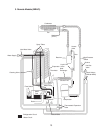
I. Construction and Water/Refrigeration Circuit Diagram ....................................................... 8
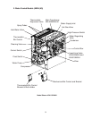
A. Construction .................................................................................................................. 8
1. Air-Cooled Models (MAH) ........................................................................................ 8
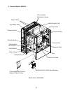
2. Water-Cooled Models (MWH(-M)) ........................................................................... 9
3. Remote Models (MRH/3) ....................................................................................... 10
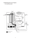
B. Water/Refrigeration Circuit Diagram .............................................................................11
1. Air-Cooled Models (MAH) .......................................................................................11
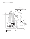
2. Water-Cooled Models (MWH(-M)) ......................................................................... 12
3. Remote Models (MRH/3) ....................................................................................... 13
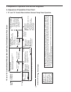
II. Sequence of Operation and Service Diagnosis ............................................................... 14
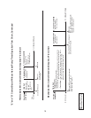
A. Sequence of Operation Flow Chart ............................................................................. 14
1. "E" and "G" Control Board without Harvest Pump Timer Operation ....................... 14
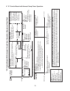
2. "G" Control Board with Harvest Pump Timer Operation ....................................... 16
B. Service Diagnosis ....................................................................................................... 17
1. "E" and "G" Control Board without Harvest Pump Timer Diagnosis ....................... 18
2. "G" Control Board with Harvest Pump Timer Diagnosis ........................................ 24
C. Control Board Check ................................................................................................... 30
D. Bin Control Check ....................................................................................................... 31
1. Thermostatic Bin Control Check ............................................................................ 31
2. Mechanical Bin Control Check and Cleaning ....................................................... 32
E. Float Switch Check and Cleaning ............................................................................... 34
1. Float Switch Check ................................................................................................ 34
2. Float Switch Cleaning ............................................................................................ 35
F. Thermistor Check ......................................................................................................... 36
G. Diagnostic Tables ........................................................................................................ 37
III. Controls and Adjustments ............................................................................................... 41
A. Control Board Layout .................................................................................................. 42
1. "E" Control Board .................................................................................................. 42
2. "G" Control Board ................................................................................................. 43
B. LED Lights and Audible Alarm Safeties ....................................................................... 44
1. "E" Control Board .................................................................................................. 44
2. "G" Control Board ................................................................................................. 45
C. Settings and Adjustments ............................................................................................ 46
1. Default Dip Switch Settings .................................................................................... 46
a) "E" and "G" Control Board without Harvest Pump Timer Operation .................. 46
b) "G" Control Board with Harvest Pump Timer Operation .................................... 46
2. Harvest Timer (S4 dip switch 1 & 2) ...................................................................... 47
3. Pump-Out Timer (S4 dip switch 3 & 4) .................................................................. 47
4. Pump-Out Frequency Control (S4 dip switch 5 & 6) .............................................. 48
IMPORTANT
This manual should be read carefully before the appliance is serviced. Read
the warnings and guidelines contained in this manual carefully as they provide
essential information for the continued safe use, service, and maintenance of the
appliance. Retain this manual for any further reference that may be necessary.