


14
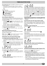
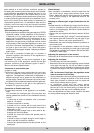
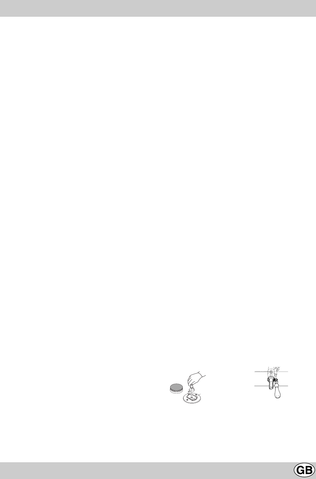
fig.9
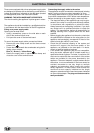
fig.10
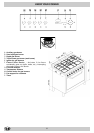
INSTALLATION
A
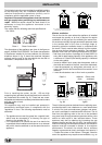
open window or a more efficient ventilation system by
increasing the extraction power of the electric fan if installed.
Liquid petroleum gas descends towards the floor as it is
heavier than air. Apertures in the outside walls in rooms
containing LPG cylinders should therefore be at floor level,
in order to allow any gas from leaks to be expelled. Do not
store LPG cylinders (even when empty) in basements or
rooms below ground level; it is advisable to keep only the
cylinder in use in the room at any one time and connected
far from heat sources which could raise its temperature to
above 50 °C.
Gas connection for the gas hob
The hob should be connected to the gas supply by a CORGI
registered installer. During installation of this product it
is essential to fit an approved gas tap to isolate the
supply from the appliance for the convenience of any
sebsequent removal or servicing. Connection of the
appliance to the gas mains or liquid gas must be carried
out according to the prescribed regulations in force, and
only after it has been ascertained that it is adaptable to
the type of gas to be used. If not, follow instructions
indicated in the paragraph headed, 'Adapting to different
types of gas'.
In the case of connection to liquid gas, in a cylinder, a
pressure regulator, that conform to the regulations in
force, must be inserted.
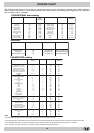
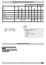
Important: for safety, for the correct regulation of gas
use and long life of the appliance, ensure that the gas
pressure conforms to the indications given in table 1,
'Burner and Nozzle Specifications'.
Connection to non-flexible tube
(copper or steel)
Connection to the gas source must be done in such a way
as to not create any stress points at any part of the
appliance. The appliance is fitted with an adjustable, 'L'
shaped connector and a gasket for the attachment to
the gas supply. Should this connector have to be turned,
the gasket must be replaced (supplied with the apliance).
The feeding connector of the gas to the appliance is
threaded 1/2" gas male cylinder.
Connection to flexible steel tube
The gas feed connector to the appliance is a threaded,
male
1/2" connector for round gas pipe. Only use pipes and
sealing gaskets that conform to the standards currently
in force.
• it should be as short as possible, with a maximum
length of 1.5 metres;
• it should not be bent or kinked;
• it should not be in contact with the rear panel of the
appliance or in any case with parts which may reach a
temperature of 50°.
• it should not pass through holes or slits used for dis-
charging the oven flue gases;
• it should not come into contact with pointed parts or
sharp corners;
• it should be easy to inspect along its entire length in
order to be able to check its condition;
• it should be replaced before the date printed on the
actual pipe.
Check the seal
Upon completion of installation, check for leaks from the
gas circuit using a soapy water solution (never use a
flame). Make sure that the natural gas pipe is adequate
for a sufficient supply to the appliance when all the
burners are lit.
Adapting to different types of gas (instructions for the
hob)
To adapt the hob to a different type of gas from the factory-
set one (indicated on the rating plate at the top of the
hood or on the packaging), the burner nozzles should be
replaced as follows:
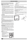
• Remove the pan supports and slide the burners off their
seats.
• Unscrew the nozzles (fig. 9, using a 7 mm socket spanner
and replace them with nozzles for the new type of gas
(see table 1 "Burner and nozzle specifications").
• Reassemble the parts following the above procedure in
the reverse order.
• On completion of this operation, replace the old rating
label with the one indicating the new type of gas used.
This sticker is available from Hotpoint Service (see KEY
CONTACTS, back page).
Adjusting the primary air of the burners
The primary air of the burners does not need to be adjusted.
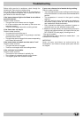
Adjusting the low flame
• Turn the tap to the low flame position;
• Remove the knob and turn the adjusting screw, situated
to the right of the tap (fig. 10) until you obtain a regular
small flame, using a screwdriver (loosening the screw
increases the height of the flame, tightening decreases
it).
N.B.: In the case of liquid gas, the regulation screw
must be screwed in all the way.
• Having obtained the low flame setting required and with
the burner lit, change the position of the knob several
times from minimum to maximum and vice versa and
check that the flame does not go out.
• In appliances fitted with the safety device
(thermocouple), should the device fail to work with the
burners set to the low flame setting, increase the low
flame setting of the same on the adjusting screw.
Once the adjustment has been made, remount the seals
on the by-passes using leak detection fluid.