


Rev.0301
7
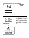
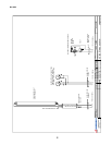
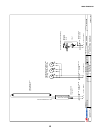
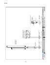
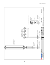
WIRING COLOR CODE
GREEN GROUND
PURPLE ANTI-SWEAT
ORANGE LIGHTS
YELLOW RECEPTACLE
RED / BLACK T-STAT /SOLENOID230V
BLACK / WHITE T-STAT / SOLENOID 115V
BROWN FAN MOTORS
CASE MUST BE GROUNDED
NOTE: Refer to label affixed to case to determine the actual
configuration as checked in the “TYPE INSTALLED” boxes.
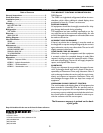
Electrical Circuit Identification
Standard lighting for all models will be full length fluores-
cent lamps located on the front of the parent case.
The switch controlling the lights is located on the parent
case.
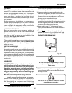
BEFORE SERVICING
ALWAYS DISCONNECT ELECTRICAL
POWER AT THE MAIN DISCONNECT
WHEN SERVICING OR REPLACING ANY
ELECTRICAL COMPONENT.
This includes (but not limited to) Fans, Heat-
ers, Thermostats, and Lights.
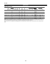
FIELD WIRING & SERIAL PLATE AMPERAGE
Field Wiring must be sized for component amperes
printed on the serial plate. Actual ampere draw may be
less than specified. Field wiring from the refrigeration
control panel to the merchandisers is required for re-
frigeration thermostats. Most component amperes are
listed in the “Case Specs” section, but always check the
serial plate.
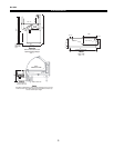
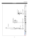
BALLAST LOCATION
Ballasts are located within the access panel that runs
the length of the rear of the case. Refer to diagram on
page 6.
Electrical
panel and whether the case is going to be pushed up against
a wall.
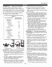
Ballast and T-stat are located in the front left hand area
of the case, viewed from customer angle.
Front of Case
In all cases, the thermostat is located on the same side of
the case. If you are looking at the case from the front, it is
the right-hand side. If you are looking at the case from the
back, it is the left-hand side.
Attention Installer!
It is contractor’s responsibility to install case(s)
according to