


Rev.0008
3
HUSSMANN CHINO PRODUCT CONTROL
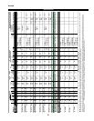
The serial number and shipping date of all equipment has
been recorded in Hussmann’s files for warranty and re-
placement part purposes. All correspondence pertaining
to warranty or parts ordering must include the serial num-
ber of each piece of equipment involved, in order to pro-
vide the customer with the correct parts.
The Hussmann warranty is printed on the back
of this guide.
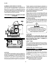
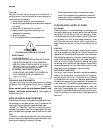
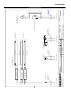
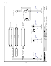
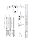
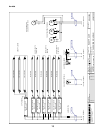
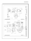
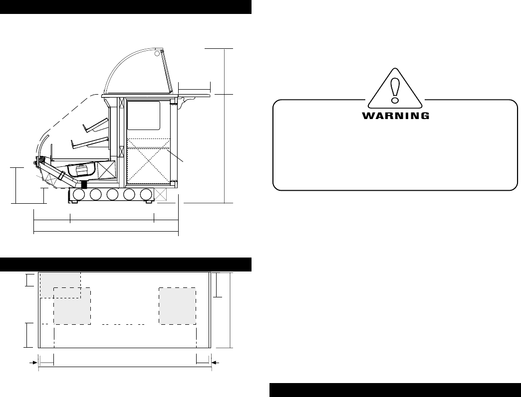
Cut & Plan Views
Plan View
48"
1"
1"
8"
8’-2" (4’-2”, 6’-2”)
CASE FRONT
8"
16"
8"
REFRIG.
MECHANICAL
STUB UP AREA
none
16"
Ref. Dome
(Optional)
Light
RGSSFP (S.C)
shown with Optional Refrigerated Rear Storage
Prep/Self-Service
*3
6
"
4
8
"
End
Panel
*1
2
"
1
2
"
30"
Adj. Wire
Racks
Coil
8
1
/
4
"
1
3
"
8"
12"
19
1
/
2
"
*5
"
Elec.
Access
9
7
/
8
"
Condensing
Unit
S.C.
CONDENSING
UNIT
DRAIN & ELEC.
MECHANICAL
STUB UP AREA
18" X 18"
In-
stallation
LOCATION
The refrigerated merchandisers have been designed for
use only in air conditioned stores where temperature and
humidity are maintained at or below 75°F and 55% rela-
tive humidity. DO NOT allow air conditioning, electric fans,
open doors or windows (etc.) to create air currents around
the merchandiser, as this will impair its correct operation.
Product temperature should always be maintained at a
constant and proper temperature. This means that from
the time the product is received, through storage, prepa-
ration and display, the temperature of the product must
be controlled to maximize life of the product.
UNCRATING THE STAND
Place the fixture as close to its permanent position as
possible. Remove the top of the crate. Detach the walls
from each other and remove from the skid. Unbolt the
case from the skid. The fixture can now be lifted off the
crate skid. Lift only at base of stand!
EXTERIOR LOADING
These models have not been structurally designed to sup-
port excessive external loading. Do not walk on their
tops; This could cause serious personal injury and dam-
age to the fixture.
AVOID REMOVING CONCRETE
All cases were leveled and joined prior to shipment to
ensure closest possible fit when cases are joined in the
field. To avoid removing concrete flooring, begin
lineup at highest point of store floor.
LEVELING
IMPORTANT! It is imperative that the case
be leveled from front to back and side to side
prior to joining. A level case is necessary to
insure proper operation.
JOINT TRIM
After the case has been leveled and joined, and refrigera-
tion, electrical, and waste piping work completed, install
the splashguards. Fasten along the top edge, or center, with
#10 X 3/8" sheet metal screws.
DO NOT SEAL JOINT T RIM T O FLOOR!
Plumbing
WASTE OUTLET AND P-TRAP
The waste outlet is located off the center of the case on
one side allowing drip piping to be run lengthwise under
the fixture.
A 1-1/2" P-trap and threaded adapter are supplied with
each fixture. The P-trap must be installed to prevent air
leakage and insect entrance into the fixture.
NOTE: PVC-DWV solvent cement is recommended.
Follow the manufacturer’s instructions.