


Rev.0008
5
EXPANSION VALVE ADJUSTMENT
Expansion valves must be adjusted to fully feed the evapo-
rator. Before attempting any adjustments, make sure the
evaporator is either clear or very lightly covered with frost,
and that the fixture is within 10°F of its expected operat-
ing temperature.
MEASURING THE OPERATING SUPERHEAT
1. Determine the suction pressure with an accurate
pressure gauge at the evaporator outlet.
2. From a refrigerant pressure temperature chart,
determine the saturation temperature at the
observed suction pressure.
3. Measure the temperature of the suction gas at the
thermostatic remote bulb location.
4. Subtract the saturation temperature obtained in step
No. 2 from the temperature measured in step No. 3.
3. The difference is superheat.
5. Set the superheat for 5°F - 7°F.
NOTE: Slow air picks up more humidity from coil and ice.
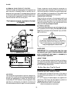
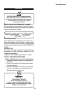
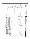
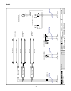
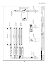
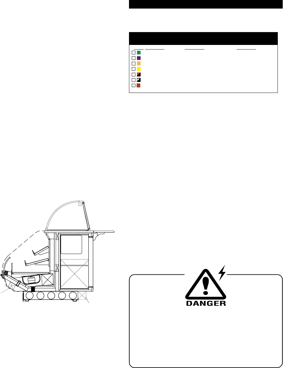
T-STAT LOCATION
T-Stats are located within the electrical raceway. at the front
of the case.
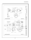
Locations for Ballast, T-Stat and Electrical
Ref. Dome
(Optional)
Light
Coil
ELEC. ACCESS
T-STAT &
BALLAST
Condensing
Unit (S.C.)
Optional Electrical
Access T-Stat and
Electrical
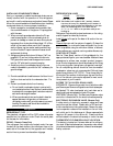
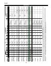
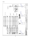
WIRING COLOR CODE
Self Contained cases are wired using a terminal block.
Remote cases are wired as follows:
Color Description Descripcion Descripcion
GROUND TIERRA MASA MASSE
ANTI-SWEAT ANTICONDENSCION ANTI-SUINTEMENT
LIGHTS LUCES ECLAIRAGE
RECEPTACLES ENCHUFER RECEPTACLE
T-STAT/SOLENOID 230 V THERMOSTATO / SOLENOID (230 VAC) SOUPAPE A SOLENOID (230 V)
T-STAT/SOLENOID 115 V THERMOSTATO / SOLENOID (115 VAC) SOUPAPE A SOLENOID (115 V)
FAN MOTORS VENTILADORES VENTILATEUR
STANDARD CASE WIRE COLOR CODE
CODIGO DE COLORES DE LOS ALAMBRES PARA LAS VITRINAS ESTANDAR
CODE COULEUR POUR FILS DE BOITIER NORMALISE
430-01-0338 r9908
CASE
MUST BE GROUNDED
NOTE: Refer to label affixed to case to determine the actual
configuration as checked in the “TYPE INSTALLED” boxes.
ELECTRICAL CIRCUIT IDENTIFICATION
Standard lighting for all models will be full length fluores-
cent lamps located within the case at the top.
The switch controlling the lights, the plug provided for
digital scale, and the thermometer are located at the rear
of the case mullion.
The receptacle that is provided on the exterior back of
these models is intended for computerized scales with a
five amp maximum load, not for large motors or other
high wattage appliances. It should be wired to a dedicated
circuit.
ELECTRICAL SERVICE RECEPTACLES
(When Applicable)
The receptacles located on the exterior of the merchan-
diser are intended for scales and lighted displays. They
are not intended nor suitable for large motors or other
external appliances.
BEFORE SERVICING
ALWAYS DISCONNECT ELECTRICAL
POWER AT THE MAIN DISCONNECT
WHEN SERVICING OR REPLACING ANY
ELECTRICAL COMPONENT.
This includes (but not limited to) Fans, Heat-
ers, Thermostats, and Lights.
FIELD WIRING & SERIAL PLATE AMPERAGE
Field Wiring must be sized for component amperes printed
on the serial plate. Actual ampere draw may be less than