


ICE Series Electrical System
Page F12
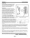
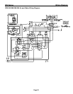
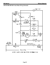
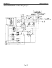
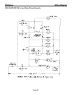
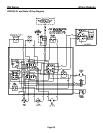
Electrical Sequence for theICE1506 Series Version 3 (Manufactured from January, 2008)
This unit incorporates a timer upstream of the Low Pressure Control for Low Ambients.
1. When the Selector Switch is set to ICE, Relay Number 2 Coil is energized through Cam Switch
contacts C and NC (Bypasses the Bin Controls)
2. Relay Number 4B contacts C and NC energize Timer Number 2 (6 Minutes)
3. Timer number 2 times out and energizes Relay Number 3 Coil.
4. Relay Number 3B contacts C and NO close and energizes the Low Pressure Control.
5. The Low Pressure Control closes to energize Timer Number 1.
6. Timer Number 1 times out and energizes Relay Number 1 Coil
7. Relay Number 1A contacts C and NO close and send power Cam Switch Number 2 C and NC
which energizes Harvest Motor 2, Hot Gas valves and Relay Number 4 Coil.
8. Relay Number 1B contacts C and NO close to energize Harvest Motor 1 and Hot Gas Valve 1.
9. When the Low Pressure Control opens during hot gas, the circuit is latched through the Purge
Switch contacts C and NC.
10. Once Cam Switch 2 contacts C and NO close (High side of the Cam) it will remain energized
from the Selector Switch until contacts C and NC close (Rotates 360 degrees)
11. Once Cam Switch 1 contacts C and NO close (High side of the Cam) the Harvest Motor will be
energized and the Water Pump, Purge Valve and Relay Number 2 Coil will be de-energized
when contacts C and NC open.
12. When Relay Number 2 Coil is de-energized and if the curtain switches or bin stat are open, the
unit will pump down and shut off on full bin.
Notes:
●C=Common
●NC=Normally Closed
●NO-Normally Open
●Relay Number 9 & 12=Common
●Relay Number 1 & 4=Normally Closed
●Relay Number 5 & 8=Normally Open
●Relay 1, Puts unit into defrosts.
●Relay 2, Bypasses the Bin Switches.
●Relay 3,Energizes the Low Pressure Control
●Relay 4,Resets Timer Number 2