


P/N 18521100738/25/94
Step Three
A
Ice Bank
Control relative
to agitator motor
angle.
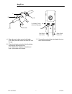
S Apply the Warning Decal (A) to the plate.
Place the plate in the unit with the decal on
the right hand side.
S Tighten the plate to the basket with the hex
nuts. Apply the three screws to each side.
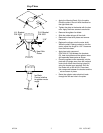
S Remove the agitator fan blade.
S Slide the rubber slinger off the shaft.
S Remove the heat sink plates and remove
the cover.
S Replace the slinger onto the motor shaft.
While the shaft is being pushed up into the
motor, adjust the slinger to 1/16I clearance
from the motor base.
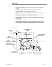
S Apply heat sink compound
(P/N 000113-734) between the brackets
(G), heat sink plates and the agitator motor
and assemble these parts as shown.
S Place the agitator motor assembly into the
plate with the angle away from the ice bank
control bulb. Mark the mounting holes (H)
using the bracket as a template. Drill the
four holes with a #29 drill bit. Place heat
sink compound between the bracket and the
plate and screw in place.
S Route the agitator motor electrical leads
through the left rear hole in the plate.
R.H. Bracket
P/N 3531
L.H. Bracket
P/N 3532
1/16I
Heat Sink
Plates
H
H
G
G