


Continuous Flow Icemaker Service Manual
Publication Number: 630460324SER - 8 - © 2006, IMI Cornelius Inc.
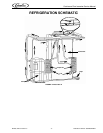
REFRIGERATION SYSTEM
REFRIGERATION SYSTEM ADJUSTMENTS
A complete understanding of the icemaker and hermetic refrigeration system is necessary before any
adjustments are made. The refrigeration technician must use high and low side pressure readings, water
and air temperatures, plus general conditions of cleanliness to assess the refrigeration system status
when making any adjustments.
All icemaker products are tested and adjusted at the factory prior to shipment where the ambient
temperature ranges from 650F to 900F, depending on the season of the year.
Whenever a new icemaker is initially installed and started-up, it is imperative that the start-up operator
make the following checks and readjustments for local conditions.
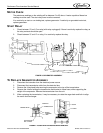
PUMPDOWN CYCLE
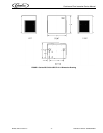
The Series1400 unit is a split system. The icemaker consists of two gearmotor/evaporator assemblies
and a liquid line solenoid. The condensing unit consists of a compressor, condenser, fan motor and
receiver. The icemaker is designed for indoor use only. The condensing unit is designed for outdoor use.
The two units are connected with a precharged line kit.
The system operates on a pump down cycle. When the bin thermostat senses ice it opens the circuit to
the liquid line solenoid. The liquid line solenoid closes and stops the flow of refrigerant to the evaporators.
This causes the suction pressure to drop. The condensing unit is shut off when the suction pressure
drops below 5 psig. The low-pressure control should be adjusted to open between 0-5 psig and close
between 15-20 psig. Note: there is no electrical connection between the two units.
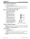
EXPANSION VALVE
You will find a thermal expansion valve on icemakers, which is used to control the amount of refrigerant
flowing through the evaporator. Improperly installed or defective expansion valves may cause low
production, soft ice, squeaking from evaporator and excessive load inside evaporator.
By using general refrigeration trouble shooting along with the pressure charts, you can easily determine
whether or not the expansion valve is working properly.
NOTE: Units with thermostatic expansion valve, the valve is located on bottom refrigerant line.
Sensing bulb is located on top refrigerant line.
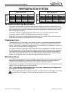
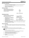
Very high discharge pressure is present in system. Quick disconnects on your gages will minimize
Danger and loss of refrigerant. Comply with federal regulations for reclaiming refrigerant.
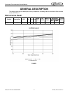
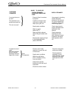
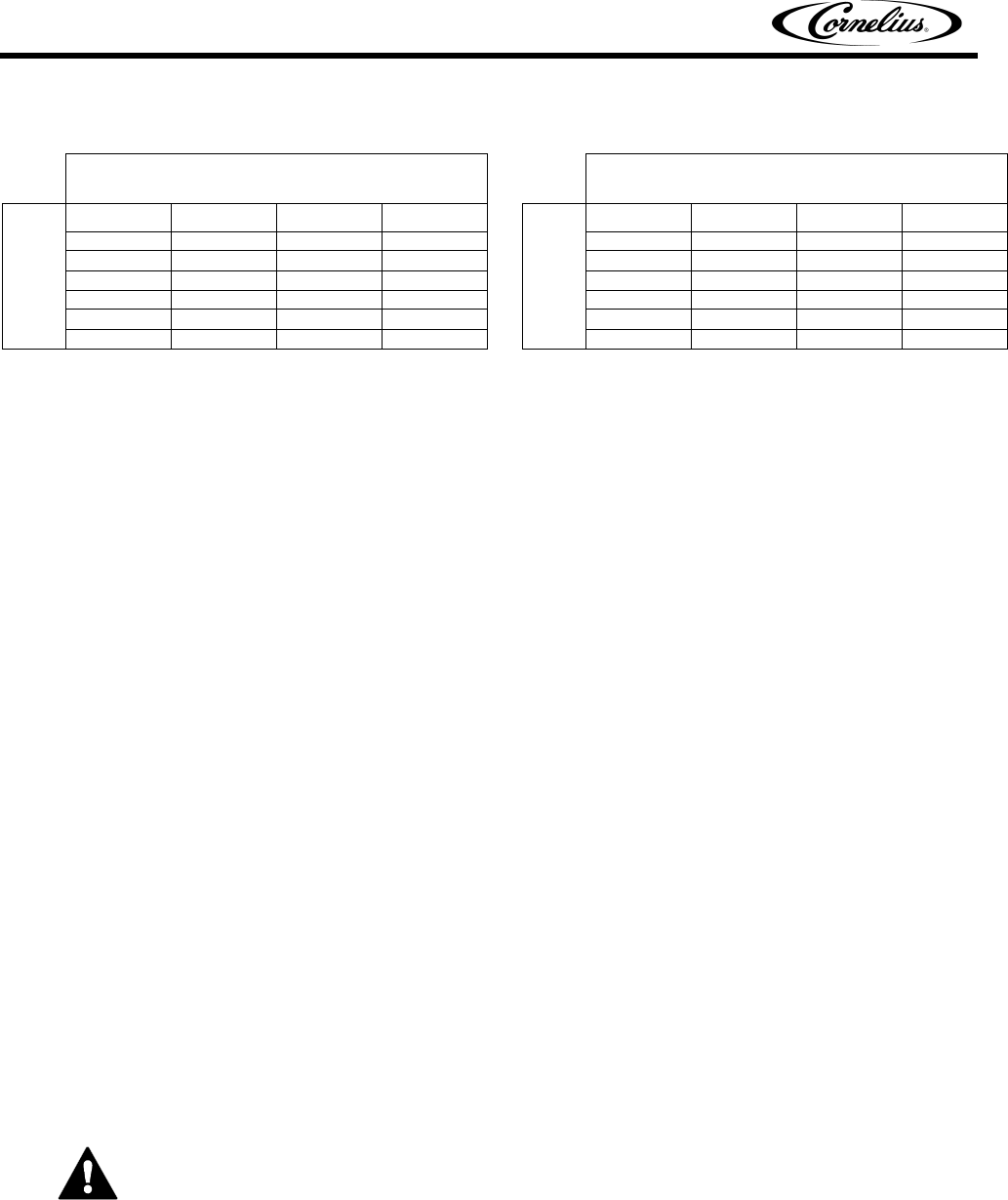
Suction Pressure +- 2 lb.
Water Temperature
Discharge Pressure +- 10 lbs.
Water Temperature
AIR TEMP.
50° 70° 90°
AIR TEMP
50° 70° 90°
50° 18 18 18 50° 213 213 213
60° 20 20 20 60° 220 220 220
70° 20 20 20 70° 225 225 226
80° 21 21 21 80° 230 230 231
90° 23 23 23 90° 251 251 252
105° 27 27 27 105° 302 302 303