


7
SECTION 2: INSTALLATION/OPERATION INSTRUCTIONS
INSTALLATION INSTRUCTIONS (CONTINUED)
Mount all dispensing equipment at back of machine or on adjacent wall. Do not mount equipment on top or front of machine.
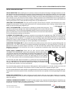
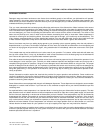
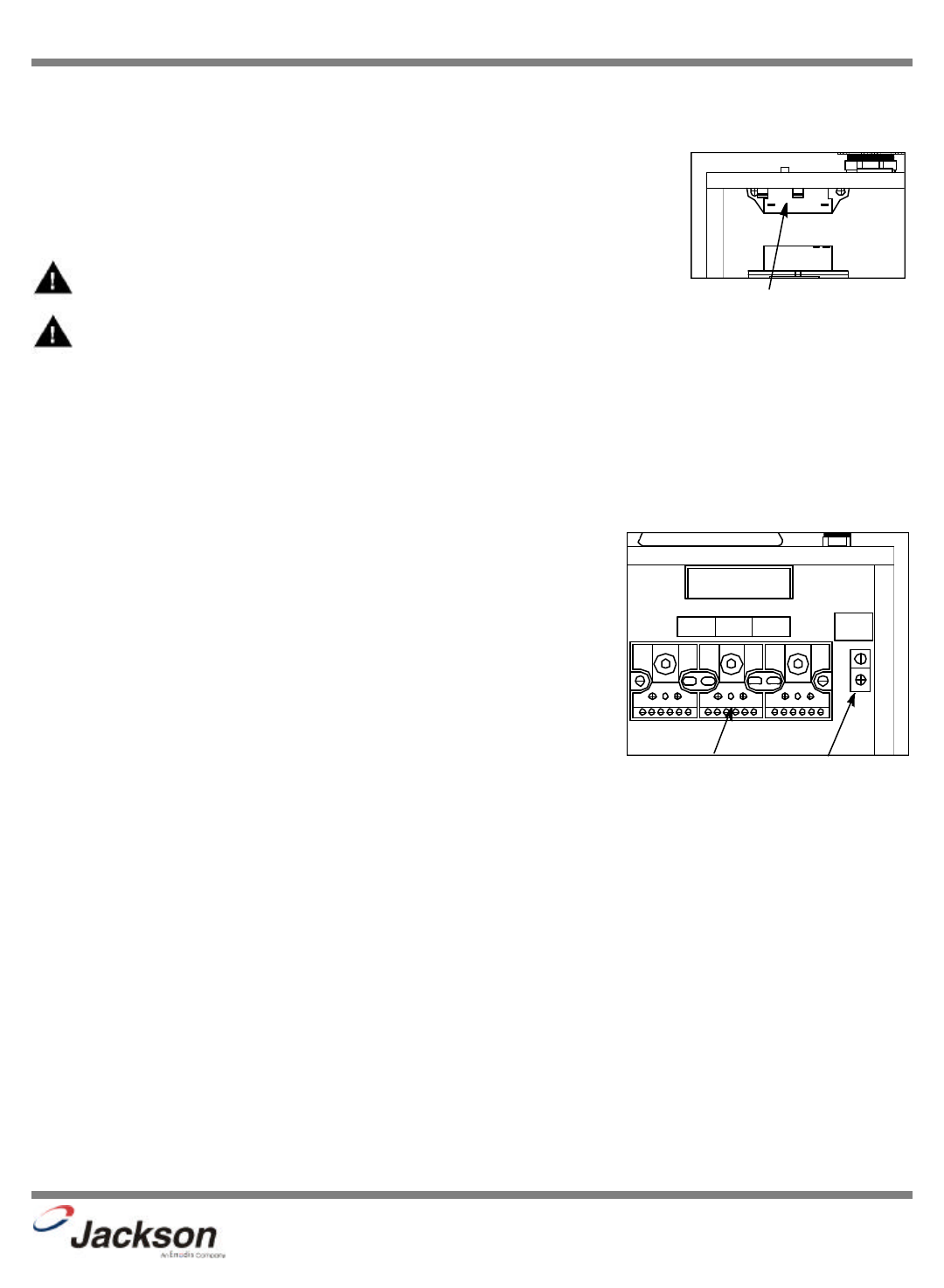
A fuse block is provided and located at the rear of the control box for electrical power connec-
tion and will provide line voltage (208/230V) during sixty (60) second time cycle. Properly rated
fuses must be installed into fuse block for power connection. Install dispensing equipment
power leads to fuse block in control box. Route wires to fuse block through 1/2” conduit hole
provided in rear of control box. Install properly rated fuses not to exceed 2.5 ampere.
NOTE: This fuse block will provide constant power during sixty (60) second time cycle.
WARNING: DO NOT MAKE ANY ELECTRICAL CONNECTIONS TO ANY INPUT OR LOAD CIRCUITS OF SOLID
STATE TIMER OR ELSEWHERE IN CONTROL BOX OR TO SOLENOID OR MOTOR WIRING. CONSULT FACTORY
FOR FURTHER INFORMATION.
PLUMBING CHECK: Slowly turn on the water supply to the machine after the incoming fill line and the drain line have been
installed. Check for any leaks and repair as required. All leaks must be repaired prior to placing the machine in operation.
ELECTRICAL POWER CONNECTION: Electrical and grounding connections must comply with the applicable portions of the
National Electrical Code ANSI/NFPA 70 (latest edition) and/or other electrical codes.
Disconnect electrical power supply and place a tag at the disconnect switch to indicate that you are working on the circuit.
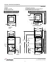
The dishmachine data plate is located on the right side and to the front of the
machine. Refer to the data plate for machine operating requirements, machine volt-
age, total amperage load and serial number.
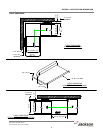
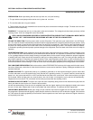
To install the incoming power lines, open the control box. This will require taking a
phillipshead screwdriver and removing the four (4) screws on the sides of the control
box. Install 3/4” conduit into the pre-punched holes in the back of the control box.
Route power wires and connect to power block and grounding lug. Install the service
wires (L1, L2, and L3 (3 phase only)) to the appropriate terminals as they are marked
on the terminal block. Install the grounding wire into the lug provided. Tighten the con-
nections. It is recommended that “DE-OX” or another similar anti-oxidation agent be
used on all power connections.
VOLTAGE CHECK: Ensure that the power switch is in the OFF position and apply power to the dishmachine. Check the incom-
ing power at the terminal block and ensure it corresponds to the voltage listed on the data plate. If not, contact a qualified ser-
vice agency to examine the problem. Do not run the dishmachine if the voltage is too high or too low. Shut off the service break-
er and mark it as being for the dishmachine. Advise all proper personnel of any problems and of the location of the service
breaker. Replace the control box cover and tighten down the screws.
200 Series Technical Manual
7610-100-45-00 Rev. E (02/10/2006)
GND
L
1
2
L
3
L
USE COPPER
CONDUCTORS ONLY
Power Block Connection
Fuse block location
Ground Lug