


VISUAL INSPECTION: Before installing the unit, check the container and machine for damage. A damaged container is an indi-
cator that there may be some damage to the machine. If there is damage to both the container and machine, do not throw away
the container. The dishmachine has been inspected and packed at the factory and is expected to arrive to you in new, undam-
aged condition. However, rough handling by carriers or others may result in there being damage to the unit while in transit. If
such a situation occurs, do not return the unit to Jackson; instead, contact the carrier and ask them to send a representative to
the site to inspect the damage to the unit and to complete an inspection report. You must contact the carrier within 48 hours of
receiving the machine. Also, contact the dealer through which you purchased the unit.
UNPACKING THE DISHMACHINE: Once the machine has been removed from the container, ensure that there are no miss-
ing parts from the machine. This may not be obvious at first. If it is discovered that an item is missing, contact Jackson imme-
diately to have the missing item shipped to you.
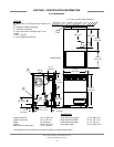
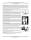
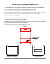
LEVEL THE DISHMACHINE: The dishmachine is designed to operate while being level.
This is important to prevent any damage to the machine during operation and to ensure the
best results when washing ware. The unit comes with adjustable bullet feet, which can be
turned using a pair of channel locks or by hand if the unit can be raised safely. Ensure that
the unit is level from side to side and from front to back before making any connections.
PLUMBING THE DISHMACHINE: All plumbing connections must comply with all applica-
ble local, state, and national plumbing codes. The plumber is responsible for ensuring that
the incoming water line is thoroughly flushed prior to connecting it to any component of the
dishmachine. It is necessary to remove all foreign debris from the water line that may poten-
tially get trapped in the valves or cause an obstruction. Any valves that are fouled as a result
of foreign matter left in the water line, and any expenses resulting from this fouling, are not
the responsibility of the manufacturer.
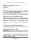
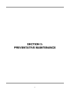
CONNECTING THE DRAIN LINE: The JP-24 series machines are a pumped (pressure)
drain capable of pumping waste water to a height of 24 inches from the floor to the kitchen’s
drain system. The dishmachines are supplied with a 10 foot long hose that extends from the
rear side of the machine. There must also be an air gap between the machine drain line and
the floor sink or drain. If a grease trap is required by code, it should have a flow capacity of
12 gallons (45.6 Liters) per minute.
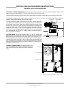
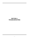
WATER SUPPLY CONNECTION: Ensure that you have read the section entitled “PLUMB-
ING THE DISHMACHINE” above before proceeding. Install the water supply line (1/2” ID
pipe size minimum) to the dishmachine line y-strainer using copper pipe. It is recommend-
ed that a water shut-off valve be installed in the water line between the main supply and the
machine to allow access for service. The water supply line is to be capable of 20A5 PSI
“flow” pressure at the recommended temperature indicated on the data plate.
Do to areas where the water pressure fluctuates or is greater than the recommended pres-
sure, it is recommended installing a water pressure regulator. Do not confuse static pressure
with flow pressure. Static pressure is the line pressure in a “no flow” condition (all valves and
services are closed). Flow pressure is the pressure in the fill line when the fill valve is
opened during the cycle.
It is also recommended that a shock absorber (not supplied) be installed in the incoming
water line. This prevents line hammer (hydraulic shock), induced by the solenoid valve as it
operates, from causing damage to the equipment.
PLUMBING CHECK: Slowly turn on the water supply to the machine after the incoming fill
line and the drain line have been installed. Check for any leaks and repair as required. All
leaks must be repaired prior to placing the machine in operation.
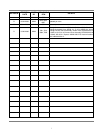
JP-24 Technical Manual 7610-002-49-79 Rev. D
Issued: 03-06-2006 Revised: N/A
SECTION 2: INSTALLATION/OPERATION INSTRUCTIONS
INSTALLATION INSTRUCTIONS
6
Adjustable Bullet Foot
Incoming Plumbing Y-Strainer
Back of Machine Showing Drain Hose
Drain Hose