


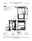
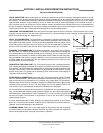
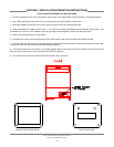


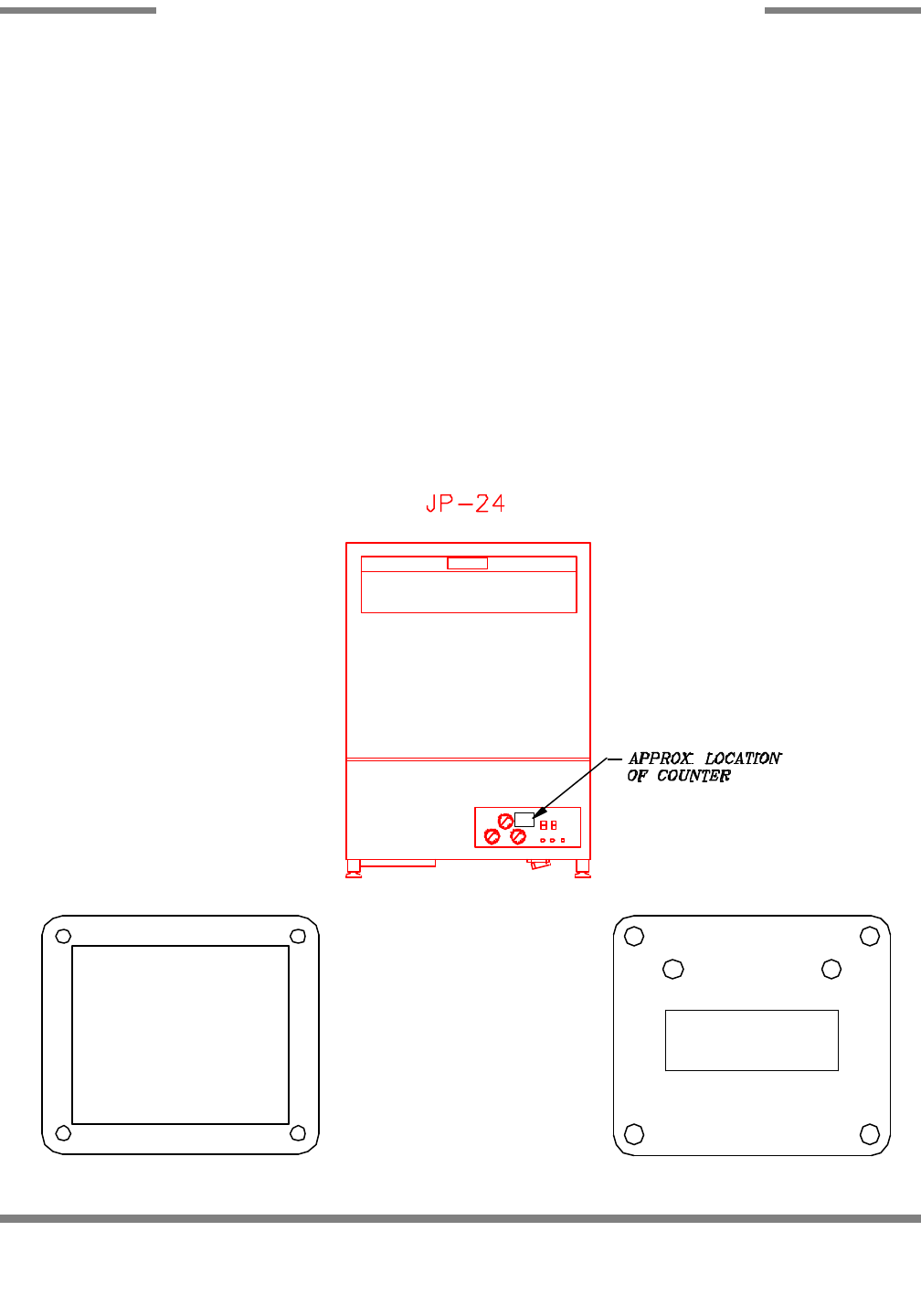
1. Locate the template on the front of the plastic control panel in the approximate location as shown in the diagram below.
2. Use a 3/32" diameter drill bit to drill the four mounting holes through the plastic control panel.
3. Mount the template to the front of the control panel using the screws and locknuts provided.
4. Using the template as a guide, cut the 1-3/8" x 1-1/8" cutout (the inside of the template) from the plastic control panel. Use
a Dremel tool (or similar) or drill multiple holes along the edge of the template in order to cut away the cutout.
5. Remove the template from the control panel.
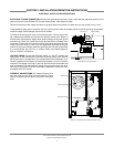
6. Assemble the counter (with mounting plate) to the control panel using the four screws and locknuts provided.
7. One lead wire from the counter is connected together with the blue wires from the fill solenoid valve and the rinse/fill light
(using the existing wire nut that connects these two wires together).
8. The other lead wire from the counter is connected together with the red wires from the fill solenoid valve and the rinse/fill
light (using the existing wire nut that connects these two wires together).
9. The counter should increment each time the fill solenoid valve is turned on.
JP-24 Technical Manual 7610-002-49-79 Rev. D
Issued: 03-06-2006 Revised: N/A
SECTION 2: INSTALLATION/OPERATION INSTRUCTIONS
CYCLE COUNTER RETROFIT KIT INSTRUCTIONS
10
Template, Cycle Counter Mount Cycle Counter Mount