


ELECTRICAL POWER CONNECTION: Electrical and grounding connections must comply with the applicable portions of the
National Electrical Code ANSI/NFPA 70 (latest edition) and/or other electrical codes.
Disconnect electrical power supply and place a tag at the disconnect switch to indicate that you are working on the circuit.
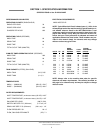
The dishmachine data plate is located on the front of the machine. Refer to the data plate for machine operating requirements,
machine voltage, total amperage load and serial number.
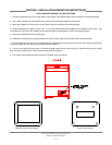
To install the incoming power lines, remove the kick panel. This will require tak-
ing a phillips head screwdriver and removing the two screws at the bottom of
the kick panel; open the door slightly while carefully lifting the kick panel up and
out of the way. Install 3/4” conduit into the pre-punched holes in the back of the
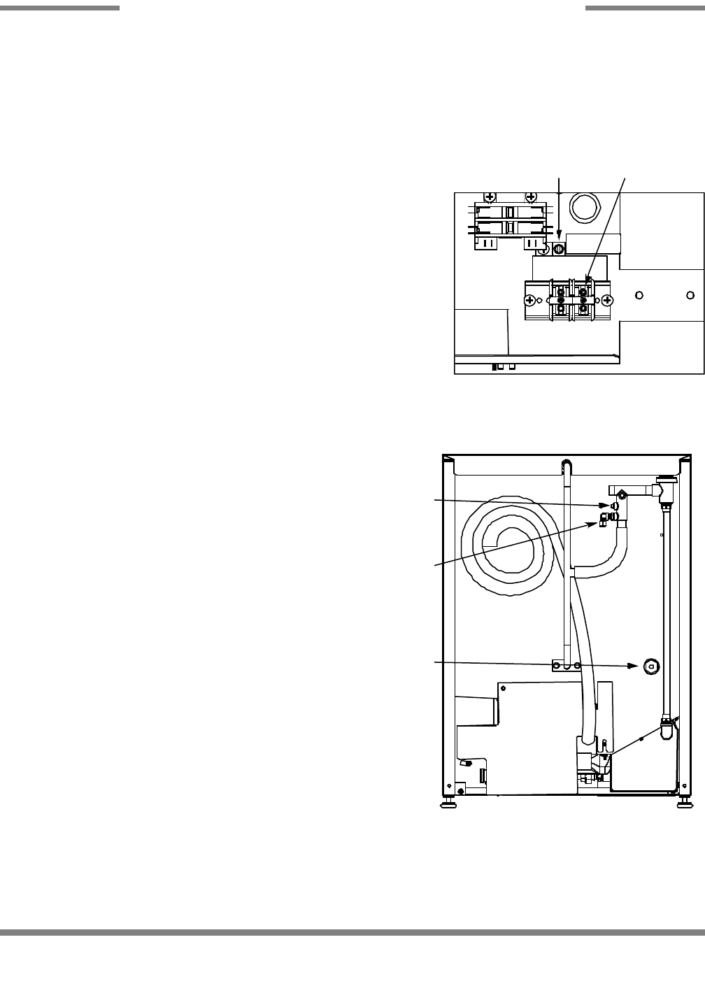
control box. Route power wires and connect to power block and grounding lug.
Install the service wires (L1 and L2) to the appropriate terminals as they are
marked on the terminal block. Install the grounding wire into the lug provided.
It is recommended that “DE-OX” or another similar anti-oxidation agent be
used on all power connections.
VOLTAGE CHECK: Ensure that the power switch is in the OFF position and
apply power to the dishmachine. Check the incoming power at the terminal
block and ensure it corresponds to the voltage listed on the data plate. If not,
contact a qualified service agency to examine the problem. Do not run the dish-
machine if the voltage is too high or too low. Shut off the service breaker and
mark it as being for the dishmachine. Advise all proper personnel of any prob-
lems and of the location of the service breaker. Replace the control box cover
and tighten down the screws.
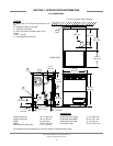
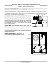
CHEMICAL CONNECTIONS: All chemical hookup loca-
tions are located on the back of the dishmachine. Please
refer to the drawing at the right for the correct connection
point.
JP-24 Technical Manual 7610-002-49-79 Rev. D
Issued: 03-06-2006 Revised: N/A
SECTION 2: INSTALLATION/OPERATION INSTRUCTIONS
ELECTRICAL INSTALLATION INSTRUCTIONS
7
Control Box Electrical Connection
Ground Lug Terminal Block
Back of Unit Showing Chemical Connection Points
Rinse Aid Fitting
Brass Plug
Detergent Fitting